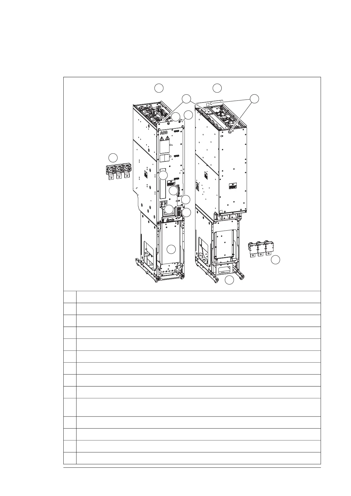
Frame R8i layout
This figure shows the layout of the R8i module.
R8i module, frontA
R8i module, backB
DC busbars1
Handle2
LEDs and fiber optic connectors3
Fan (standard speed-controlled fan shown; a direct-on-line fan is available as option +C188)4
Quick connector (three phases). The counterpart is fastened to the cabinet behind the module.5
Wheels6
Type designation label7
Terminal block [X50] (power supply for internal boards and module heating element, option +C183; DOL
fan supply, option +C188)
8
Connectors [X51], [X52], [X53]9
The unpainted grounding point (PE) between module frame and cabinet frame.10
Lifting eyes11
Circuit board compartment fan12
Operation principle and hardware description 21

 Loading...


