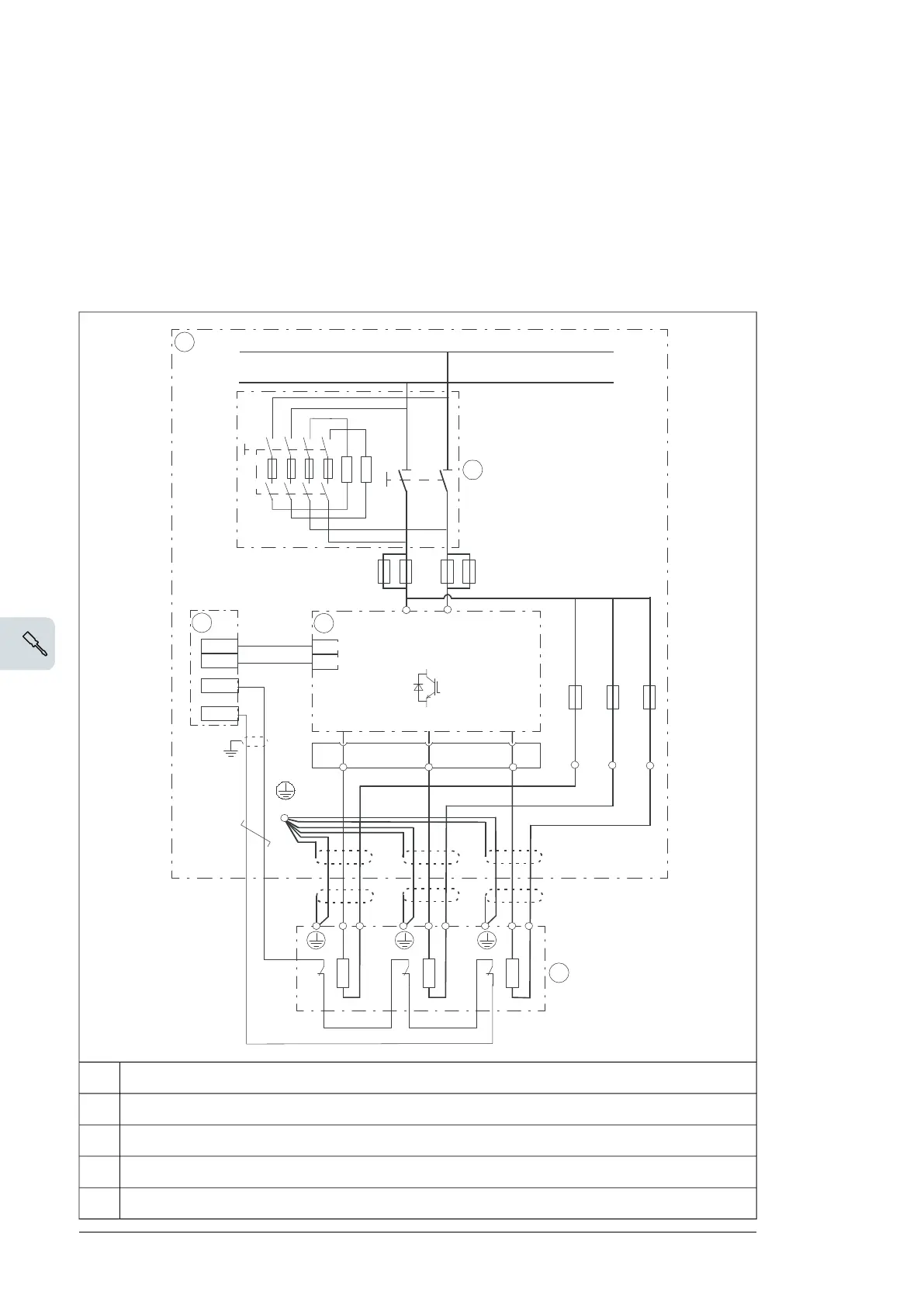
Connecting the brake resistor cables and thermal switch
■ Connection diagram
This diagram shows the brake resistor cable connections and an example connection of
the thermal switches.
The diagram also shows the internal connections of the brake chopper module cubicle to
be done by the system integrator.
9 :8
'&'&
3(
'&
'&
t
t
t
5 5 5
9
',
97
95
9
9
5 5 5
Brake chopper cubicle1
DC switch/disconnector including charging circuit2
Control unit3
Brake chopper module4
Brake resistors5
52 Electrical installation

 Loading...


