Control electronics
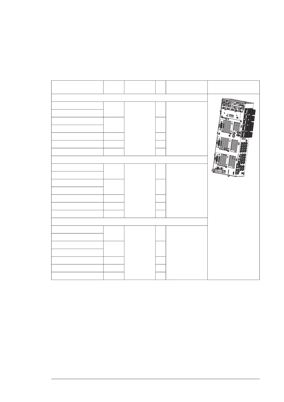
■ Control unit
You must equip each parallel-connected brake chopper module with a dedicated control
unit (and memory unit).
Illustration
Ordering codeQtyControl unit
Frame
size
Brake module type
U
N
= 400 V (Range 380 … 415 V):
3AXD50000020676
1
Control unit
BCU-02 kit
R8i
ACS880-604-0500-3
ACS880-604-0750-3
22×R8i
ACS880-604-1000-3
ACS880-604-1510-3
33×R8iACS880-604-2260-3
44×R8iACS880-604-3010-3
55×R8iACS880-604-3770-3
U
N
= 500 V (Range 380 … 500 V):
3AXD50000020676
1
Control unit
BCU-02 kit
R8i
ACS880-604-0630-5
ACS880-604-0940-5
22×R8i
ACS880-604-1260-5
ACS880-604-1880-5
33×R8iACS880-604-2830-5
44×R8iACS880-604-3770-5
55×R8iACS880-604-4710-5
U
N
= 690 V (Range 525… 690 V):
3AXD50000020676
1
Control unit
R8i
ACS880-604-0870-7
BCU-02 kit
ACS880-604-1300-7
22×R8i
ACS880-604-1730-7
ACS880-604-2600-7
33×R8iACS880-604-3900-7
44×R8iACS880-604-5200-7
55×R8iACS880-604-6500-7
The BCU-02 control unit kit contains:
• BCU-02 control unit
• memory unit with brake control program.
You must connect the control unit to each brake chopper module with a pair of fiber optic
cables. You can order them from ABB.
You can supply 24 V DC for the control unit from the brake module. Alternatively, you can
take the power supply from another suitable power source. You must acquire the cables
separately. Use a suitable standard installation cable. Use plug connector X53 for the
connection to the brake module.
Ordering information 81

 Loading...


