ControlMaster CM15 and CMF160
Universal process indicator
1
/8 DIN 4 Installation
IM/CM/I–EN Rev. P 19
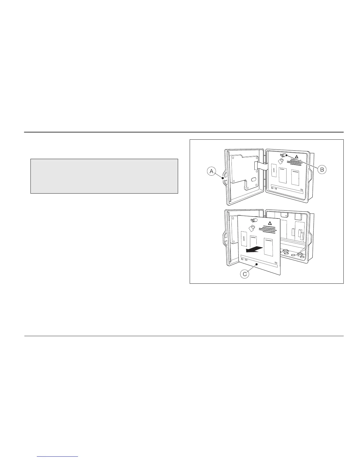
4.4.3 Accessing the Connection board –
CMF160 Indicator
Referring to Fig. 4.12:
1. Using a pozi-drive screwdriver, turn the (captive)
electronics section door retaining screw
A
1
/4 turn
counter-clockwise and open the door.
2. Turn the cover plate retaining screw
B anti-clockwise
until the cover plate
C can be removed.
3. Make connections to connection board terminals – see
Fig. 4.15, page 23.
4. Refit cover plate
C and secure it by turning retaining
screw
B clockwise until finger-tight. Close the door
and turn door retaining screw
A
1
/4 turn clockwise to
secure.
Note. Before fitting cable glands, identify the
connections required and cable gland entries to be
used.
Fig. 4.12 Accessing the CMF160 Indicator
Connection Board