ControlMaster CM15 and CMF160
Universal process indicator
1
/8 DIN Appendix B – Error Codes
96 IM/CM/I–EN Rev. P
Appendix B – Error Codes
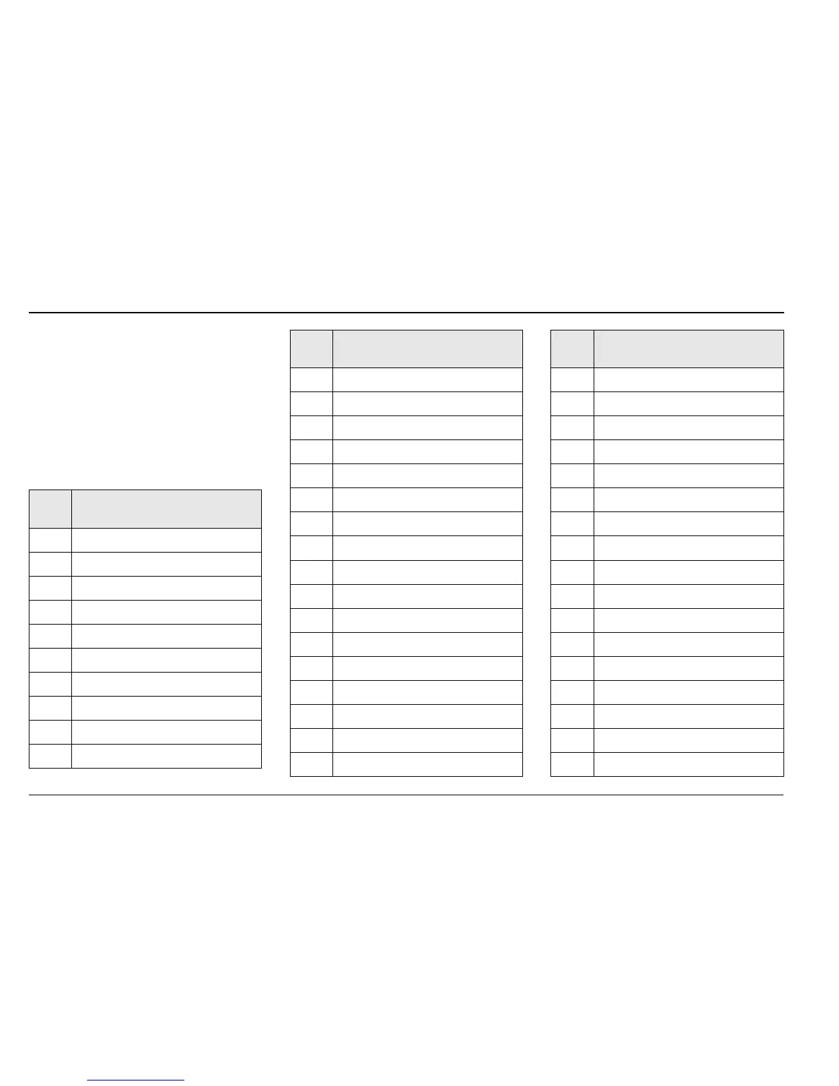
B.1 Configuration Error Codes
Configuration errors are generated
when a signal assigned as a source for
something has failed. Configuration
errors are displayed as numerical
codes and a description of each code
is shown in the following tables:
Error
Code
Error Description
1 Analog Input Value A1 (I/P 1)
2 Analog Input Value A2 (I/P 2)
3 Analog Input Value B1
4 Analog Input Value B2
5 Analog Input Value C1
6 Analog Input Value C2
22 Totalizer Batch total 1
23 Totalizer Secure Total 1
24 Totalizer Batch total 2
25 Totalizer Secure Total 2
26 Maths Block Value 1
27 Maths Block Value 2
28 Maths Block Value 3
29 Maths Block Value 4
30 Maths Block Value 5
31 Maths Block Value 6
32 Maths Block Value 7
33 Maths Block Value 8
34 Maths Block Constant 1
35 Maths Block Constant 2
36 Maths Block Constant 3
37 Maths Block Constant 4
38 Maths Block Constant 5
39 Maths Block Constant 6
40 Maths Block Constant 7
41 Maths Block Constant 8
50 PV Maximum Value 1
Error
Code
Error Description
51 PV Minimum Value 1
52 PV average Value 1
53 Volume Value 1
54 PV Maximum Value 2
55 PV Minimum Value 2
56 PV average Value 2
57 Volume Value 2
58 Customer Linearizer Value 1
59 Customer Linearizer Value 2
64 Template Block PV Value 1
65 Template Block PV Value 2
70 Analogue Input Fail State A1
71 Analogue Input Fail State A2
72 Analogue Input Fail State B1
73 Analogue Input Fail State B2
74 Analogue Input Fail State C1
75 Analogue Input Fail State C2
Error
Code
Error Description