ControlMaster CM15 and CMF160
Universal process indicator
1
/8 DIN 4 Installation
24 IM/CM/I–EN Rev. P
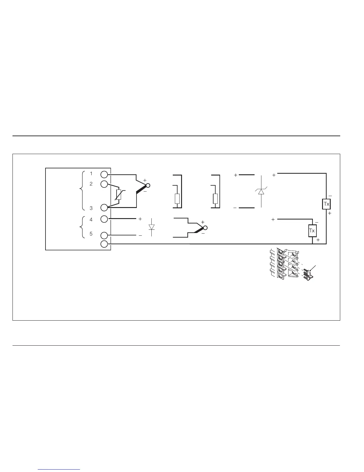
4.5.3 Analog Inputs – CM15 Indicator
Fig. 4.16 Standard Analog Inputs (1 and 2) – CM15 Indicator
mA
mV
V
Digital Input
Milliamps*
THC
CJ**
THC***
3-lead RTD
2-lead RTD +
Resistance
RTD +
RTD –
RTD +
RTD –
Transmitter PSU
Analog
Input 2
Analog
Input 1
Milliamps*
RTD –
3rd lead
CJ
Sensor
*
**
***
****
Note.
Using internal transmitter power supply.
Fit the CJ sensor supplied if Analog Input 1 or 2 are THC inputs.
(Alternatively, it is possible to use an external fixed cold [reference] junction, if the controller is
programmed for use with millivolt inputs and the appropriate thermocouple linearizer is selected.)
Analog Input 2 can be used only with THC inputs if Analog Input 1 is also used as a THC input.
For mA input types, to ensure loop continuity when the indicator is switched off, fit a 2V7 Zener diode
as shown.
3-lead RTD: 3 leads must have equal resistance, not exceeding 20 each.
****
****
mA, mV, V,
Digital Input