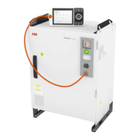
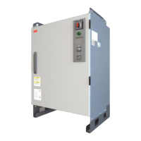
To enable the controller without any additional/external safety equipment, connect
the safety circuit as shown in the following figure.
*
A2
-X5
9
11
12
10
5
7
8
6
0V_CH1_CH2
24V_CH1
AS1/GS1+
AS1/GS1-
0V_CH1_CH2
24V_CH2
AS2/GS2+
AS2/GS2-
xx2100001568
*: The gray area on the right side of the line represents the inner side of the
controller.
In most applications it is required to connect automatic/general stop switches. It
is highly recommended to connect the stop switches as one of the following figures
Continues on next page
Product manual - OmniCore E10 89
3HAC079399-001 Revision: C
© Copyright 2019-2022 ABB. All rights reserved.
3 Installation and commissioning
3.5.8 Descriptions for connectors
Continued
 Loading...

