- 67 -
000897AG
5 - Installation
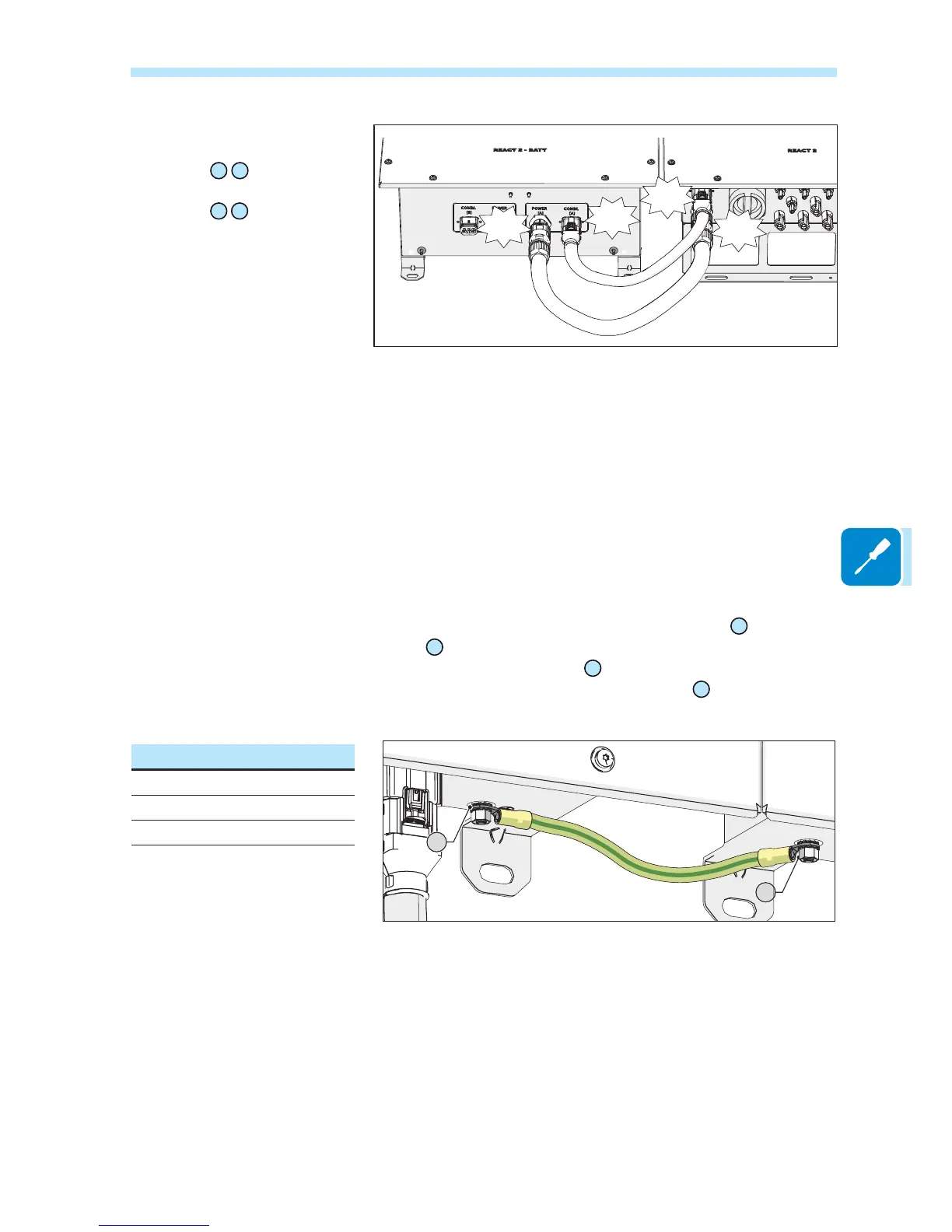
,QVWDOODQHDUWKFDEOHEHWZHHQWKHSURWHFWLYHJURXQGLQJFRQQHFWLRQSRLQWVRQWKHWZR5($&7%$77V
To execute all external grounding connection, follow the procedure described below:
)URPDPRQJWKHFRPSRQHQWVVXSSOLHG¿QGWKH0QXW0ÀDWZDVKHUDQG0VHUUDWHGORFNZDVKHUDQG
two cable lugs.
Make a jumper earth cable using the two cable lugs supplied (minimum cross-section not less than 4mm²).
The cable must be long enough to connect the REACT2-BATT external protective earth [B]
24
to the
REACT2-BATT external protective earth [A]
25
2. Connect the cable on REACT2-BATT external protective earth [B]
24
RIWKH¿UVW5($&7%$77LQVWDOOHG
3. Connect the other side of the cable on REACT2-BATT external protective earth [A]
25
For both connection follow the below installation sequence
Installation sequence:
- knurled washers
- jumper earth cable (other side)
- ÀDW washers
- M5 nut (torque of 4.1 Nm)
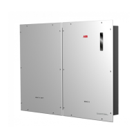
5HPRYHWKHFDSVIURPWKHEDWWHU\
connectors:
- To remove the battery signal
connectors
08
22
simply pull it.
- To remove the battery power
connectors
09
23
press the latch
(
highlighted in red) and pull it off.
&RQQHFW WKH WZR EDWWHU\ FDEOHV
between inverter and battery unit
(supplied inside the REACT2-BATT
box).
Give each cable a pull test to
FRQ¿UPWKHFRQQHFWLRQLVVHFXUH
Click
Click
COMM.
[B]
POWER
[B]
COMM.
[A]
POWER
[A]
Click
Click
25
24