- 95 -
000902AG
5 - Installation
+
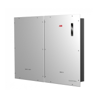
5V output connection
On the communication and control signal terminal block
40
there is
auxiliary voltage of +5V.
The maximum absorption permitted from this auxiliary power supply
voltage is 100 mA.
C
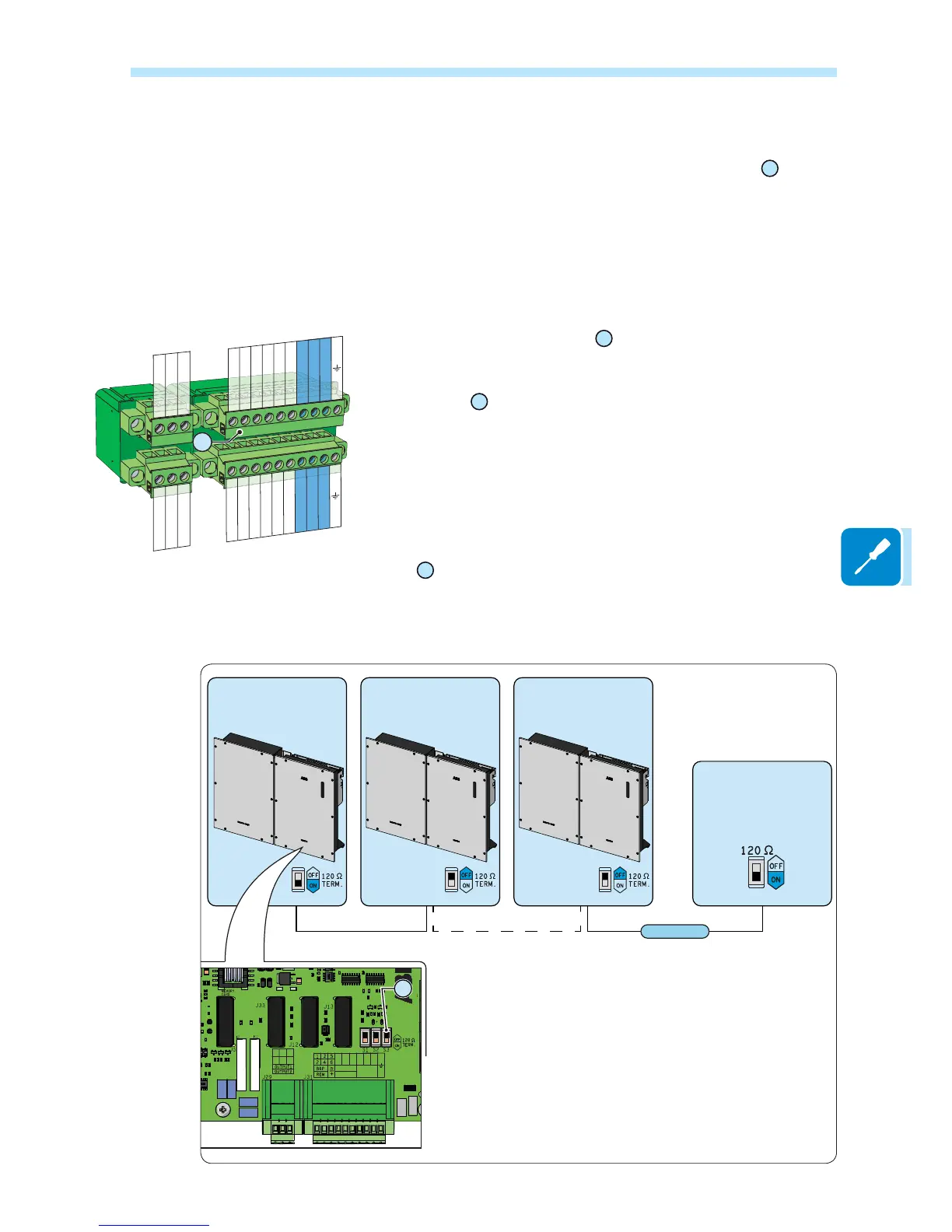
onnection of RS485 LOGGER serial communication line
The RS485 LOGGER serial communication line on the communication
and control signal terminal block
40
is reserved for the connection of
the inverter to monitoring devices that communicate with the Modbus
communication protocol. On the communication and control signal
terminal block
40
there are two connection points for each serial line
signal (+T/R, -T/R and RTN) so as to be able to make a daisy-chain
connection (“in-out”) of multiple inverters.
Connection of a monitoring system to the RS485 LOGGER communication
OLQH FRQVLVWV RI ¿UVWFRQQHFWLQJ DOO WKH XQLWVLQ WKH FKDLQ LQWKH ³GDLV\
FKDLQ´ ³LQRXW´ FRQ¿JXUDWLRQ UHVSHFWLQJ FRUUHVSRQGLQJ VLJQDOV DQG
then activating the communication line termination resistance in the last
element in the chain by setting the RS485-LOGGER line termination
switch
37
(to the ON position).
7KH FRPPXQLFDWLRQ OLQH PXVW DOVR EH WHUPLQDWHG RQ WKH ¿UVW HOHPHQW RI WKH FKDLQ ZKLFK
usually corresponds to the monitoring device.
RS485 M-B
MONITORING
SYSTEM
Modbus
S3S3 S3
METER-485
CARD
PC-485
CARD
LOGGER-485
CARD
RS485
LOGGER
RS485
METER
RS485
PC
+T/R
-T/R
RTN
+T/R
-T/R
RTN
N.C N.C
CC
N.O N.O
37
+T/R RS485 METER
BKP
BKP
+5V
-T/R RS485 METER
RTN RS485 METER
+T/R RS485 LOGGER
-T/R RS485 LOGGER
RTN RS485 LOGGER
N.C. OUTPUT 1
C OUTPUT 1
N.O. OUTPUT 1
N.C. OUTPUT 2
C OUTPUT 2
N.O. OUTPUT 2
+T/R RS485 PC
REM
REM
+5V
-T/R RS485 PC
RTN RS485 PC
+T/R RS485 LOGGER
-T/R RS485 LOGGER
RTN RS485 LOGGER
40