- 62 -
000897AG
5 - Installation
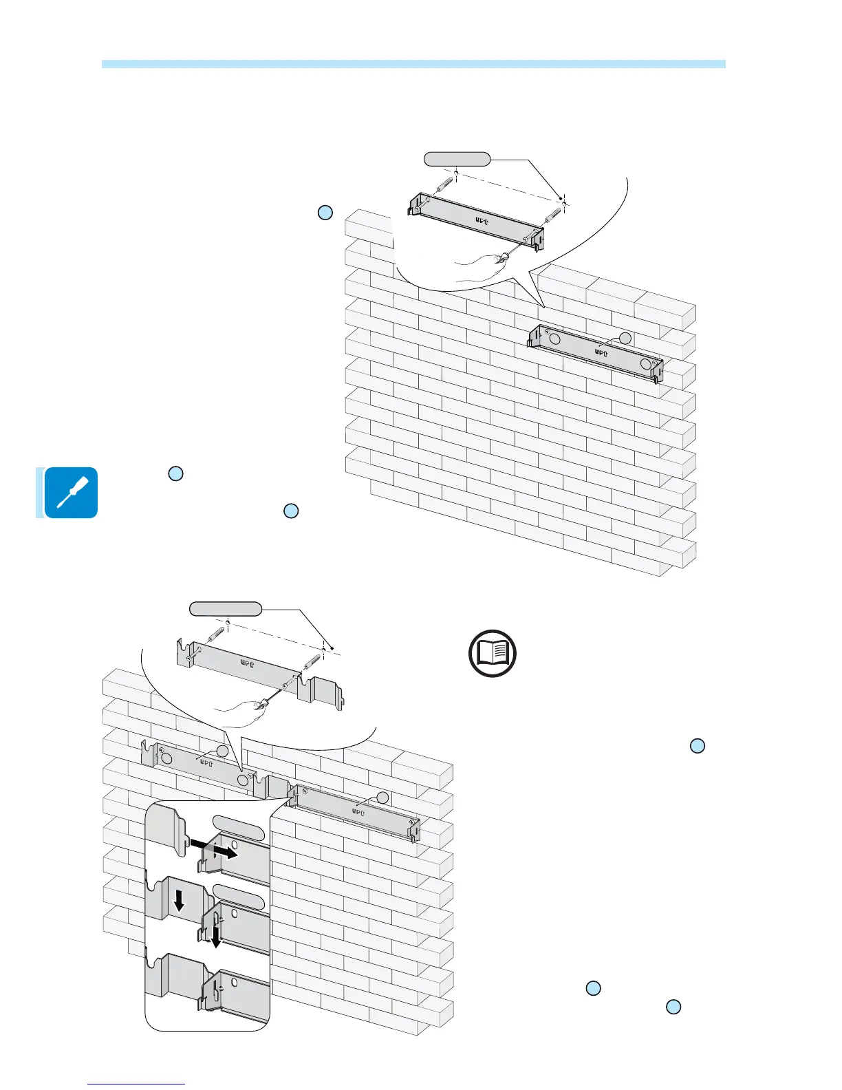
3RVLWLRQWKH5($&7812EUDFNHW
01
so that it is perfectly level on the wall
and use it as a drilling template.
,W LV WKH LQVWDOOHU¶V UHVSRQVLELOLW\ WR
choose an appropriate type of screw
anchors for the attachment points. The
choice must be based on the type of
support (wall, frame or other support),
the type of anchors to be used, and
their ability to support 4 times the
inverter’s weight (4x22Kg=88Kg).
Depending on the type of
anchor chosen, drill the required
2 holes
A
to mount the bracket.
)L[WKHREACT2-UNO bracket
01
to the
support.
The underlying procedure is related
to the side-by-side installation of
REACT2-BATT. Alternatively, is
possible to install the REACT2-BATT
separately and at greater distances
XVLQJWKH³5($&7;/&$%/(.,7´
cable kit (2 meter cables length).
3RVLWLRQ WKH 5($&7%$77 EUDFNHW
20
so
that it is perfectly level on the wall and use it as
a drilling template. To aling the two brackets
use the reference point and follow the steps
as in the picture.
,W LV WKH LQVWDOOHU¶V UHVSRQVLELOLW\ WR FKRRVH
an appropriate type of screw anchors for the
attachment points. The choice must be based
on the type of support (wall, frame or other
support), the type of anchors to be used, and
their ability to support 4 times the inverter’s
weight (4x50Kg=200Kg).
'HSHQGLQJRQWKHW\SHRIDQFKRUFKRVHQGULOO
the required 2 holes
B
to mount the bracket.
)L[ WKH 5($&7%$77 EUDFNHW
20
to the
support.
Mounting instruction - REACT2 system
01
A
A
01
20
B
B