- 74 -
000898AG
5 - Installation
C
onnection and configuration of the REACT-MTR-3PH (three-phase)
The indications set out below are necessary to connect the meter to the REACT2 system.
$OZD\VUHIHUWRWKHVSHFL¿FGRFXPHQWDWLRQVXSSOLHGZLWKWKHPHWHU
The energy meter
55
is a DIN rail device (4 modules) and must be installed
where the electricity supply is three-phase.
To avoid risks of electrical shock, all wiring operations must be carried out with the AC discon-
nect switch (or the supply meter) upstream of the meter disconnected.
'LVFRQQHFWWKH$&GLVFRQQHFWVZLWFKXSVWUHDPRIWKHPHWHU
6WULSWKHLQVXODWLRQRIWKHFDEOHIRUWKHOHQJWKZKLFKLVLQGLFDWHGRQWKH
meter (13mm).
&RQQHFWWKHFDEOHVRIWKHWKUHHSKDVHOLQHLQDFFRUGDQFHZLWKWKHOD\RXW
printed on the meter (L1, L2, L3 and N) to the three-phase connection
terminal block
56
and tighten the screws (tightening torque 2.0 Nm).
Take note of the phase to which the REACT2 system is connected; this information will be re-
quested when the system is commissioned.
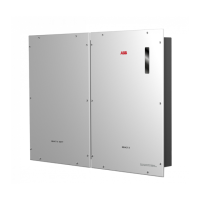
&RQQHFWWKHFDEOHVRIWKHVHULDOOLQH$%DQG&RQWKH
terminal block
57
set on the rear of the meter
55
respecting the corre-
spondence between the signals of the serial line and tighten the screws
(torque 0.25 Nm) and tighten the screws (tightening torque 0.25 Nm):
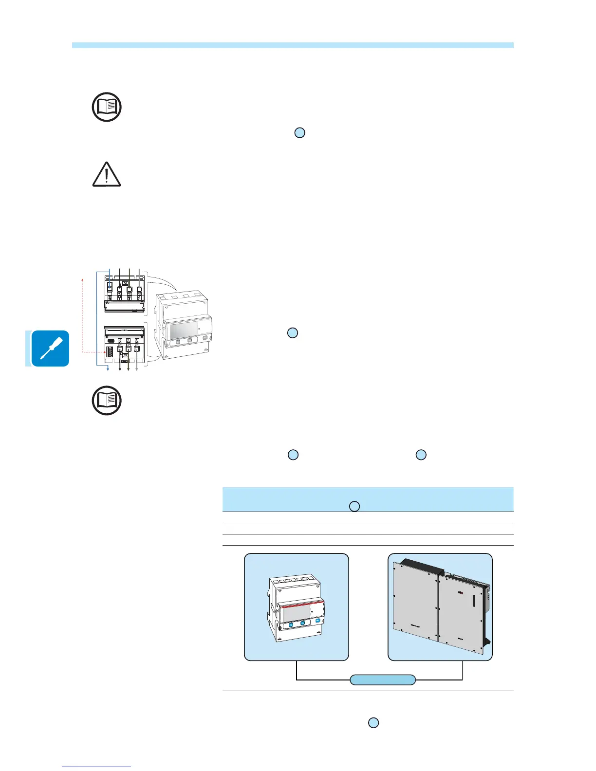
Serial line terminal block
of the meter ABB B23, B24
60
Screw terminal on the
counterpart connector
A (37) 1 (-T/R)
B (36) 3 (+T/R)
C (35) 4 (RTN)
RS485 METER
6XEVHTXHQWO\ WKH RWKHU VLGH RI WKH FDEOH PXVW EH FRQQHFWHG WR WKH
REACT2-UNO METER connector
14
4
3
3
3
COMM
69
COMM.
To REACT J3
logic board
N
N
LOADS and REACT SIDE