- 71 -
000898AG
5 - Installation
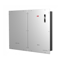
'LVFRQQHFWWKHSKDVHFDEOH/RIWKHHOHFWULFVXSSO\
,QVHUW WKH SKDVHFDEOH / WKURXJKWKH KROH PPRQ WKH 5($&7
MTR-1PH
51
. The arrow corresponding to the hole for the feeding of the
line cable
52
, indicates the direction of insertion which must be complied
with for correct measurement of the current; in fact the direction of the ar-
row indicates the supply point of the electric energy (as indicated in the
diagram).
2QFHWKHFRQQHFWLRQVWDJHLV¿QLVKHGWKHFRUUHFWLQVWDOODWLRQRIWKH
5($&70753+PXVWEHYHUL¿HG
- Power the REACT-MTR-1PH while keeping the REACT2 system off
- Action a load (of at least 50W) in the house so that the REACT-MTR-
1PH records drawing of current from the grid
- Check that the LED MEASURE (red) is permanently on. This con-
dition indicates that a drawing from the grid is recorded and so that
the reading of the direction of the current by the REACT-MTR-1PH is
correct.
Here below is set out the behaviour of LEDs on the REACT-MTR-1PH:
MEASURE LED description
Permanent Green Serial communication absent or malfunctioning
Flashing Serial communication present
STATUS LED description
Permanent red Drawing of energy from the grid
Green (steady) Self-consumption (maximum exchange ±20W)
Flashing red and
green
Feeding of energy from the grid
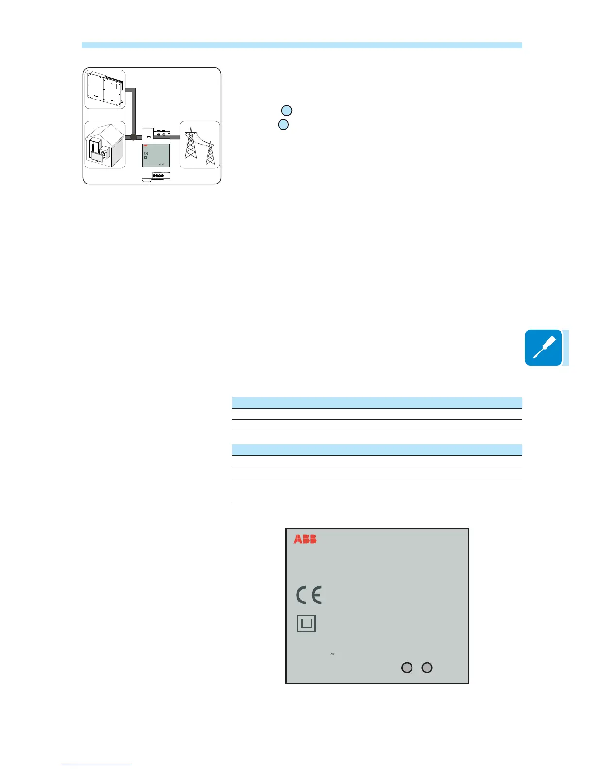
REACT-MTR-1PH
SUTATS
ERUSAEM
INPUT :
110/230 V
50/60 Hz
10 mA max
REACT-MTR-1PH
SUTATS
ERUSAEM
INPUT :
110/230 V
50/60 Hz
10 mA max