ZAngPE
ZPE
1
p1
p2
ZPE
2
p3
ZPE
3
Ohm/phase
R
jX
en07000010.vsd
IEC07000010 V2 EN
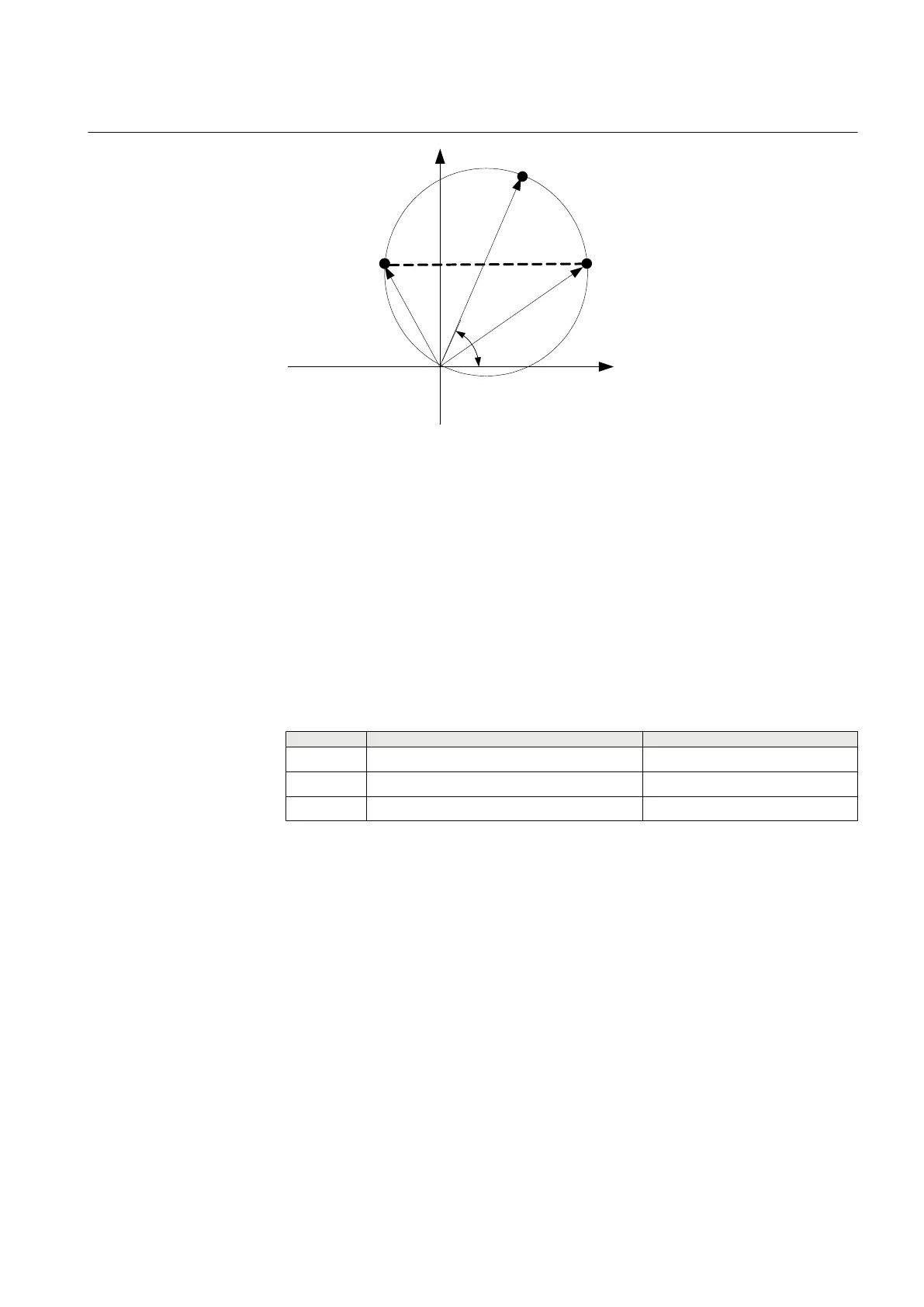
Figure 57: Proposed test points for phase-to-earth faults
Label Description
ZPE1 The measured impedance for phase-to-earth
fault at point 1 (zone reach ZPE) ohm/
phase.
ZAngPE The characteristic angel for phase-to-earth fault in degrees.
ZPE2 and ZPE3 The fault impedance for phase-to-earth fault at the boundary for the zone reach at
point 2 and 3.
Table 25: Test points for phase-to-phase loops L1-L2 (Ohm/Loop)
Test points Set Comments
1 ZPE · cos(ZAngPE) ZPE · sin(ZAngPE)
2 ZPE/2 + ΔR = (ZPE/2) · (1 - cos(ZAngPE)) ZPE/2 · sin(ZAngPE)
3 ZPE/2 - ΔR = ZPE/2 · (1 - cos(ZAngPE)) ZPE/2 · sin(ZAngPE)
Check also in the same way as for phase-to-earth fault for each test point that the
output signals STPE, START and STLx are activated where x refers to the actual
phase to be tested. After the timer tPE for the zone has elapsed, also the signals
TRIP, TRPE and TRx shall be activated.
13.5.4
Faulty phase identification with load encroachment
FMPSPDIS
There is no specific test routine for this function. The function is tested in
conjunction with other impedance (mho) functions.
1MRK 504 088-UEN C Section 13
Verifying settings by secondary injection
127
Installation and commissioning manual

 Loading...


