80 mm
View from above
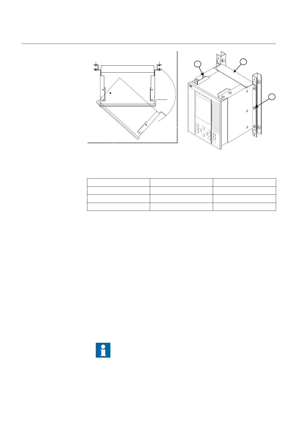
1
en06000135.vsd
3
2
IEC06000135 V1 EN
Figure 14: How to reach the connectors on the rear side of the IED.
PosNo Description Type
1 Screw M4x10
2 Screw M5x8
3 Rear protection cover -
Procedure
1.
Remove the inner screws (1), upper and lower on one side.
2. Remove all three fixing screws (2), on the opposite side, from wall support.
3. The IED can now be swung out for access to the connectors, after removing
any rear protection.
5.3.5 Side-by-side 19” rack mounting
5.3.5.1 Overview
IED case sizes, 1/2 x 19” or 3/4 x 19” and RHGS cases, can be mounted side-by-
side up to a maximum size of 19”. For side-by-side rack mounting, the side-by-side
mounting kit together with the 19” rack panel mounting kit must be used. The
mounting kit has to be ordered separately.
When mounting the plates and the angles on the IED, be sure to use
screws that follows the recommended dimensions. Using screws
with other dimensions than the original may damage the PCBs
inside the IED.
Section 5 1MRK 504 088-UEN C
Installing the IED
38
Installation and commissioning manual

 Loading...


