UL1
UL2
UL3
UN
UL1
UL1
UL2
UL3
I
E
D
T
E
S
T
S
E
T
I
E
D
IEC07000107-1-en.vsd
UL2
UL3
UN
1
2
IEC07000107 V2 EN
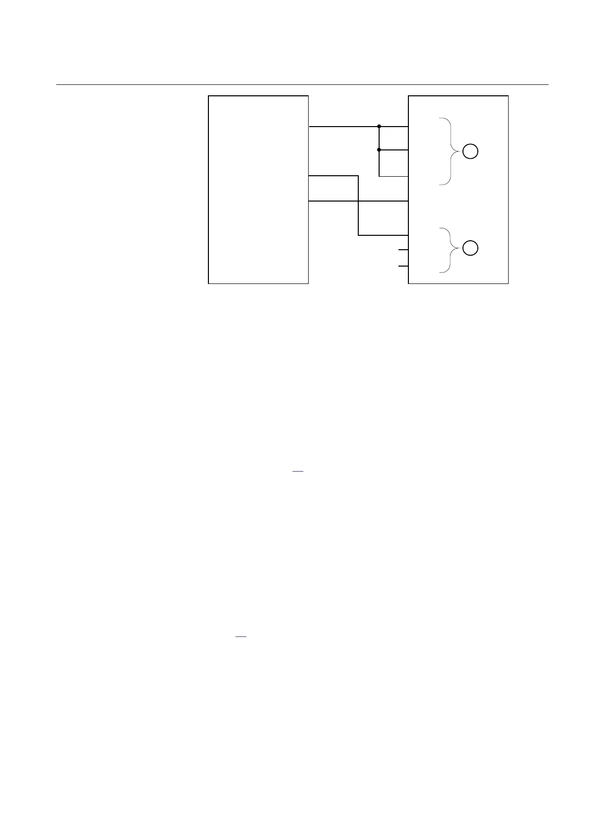
Figure 64: Connection of the test set to the IED for test of U2 block level
where:
1 is three-phase voltage group1 (U1)
2 is three-phase voltage group2 (U2)
2. Apply voltage higher than the highest set value of UDTrip, U1Low and
U2Low to the U1 three-phase inputs and to one phase of the
U2 inputs
according to figure
64.
The voltage differential
START signal is set.
3. Decrease slowly the voltage in phase UL3 of the test set until the START
signal resets.
4. Check U2 blocking level by comparing the voltage level at reset with the set
undervoltage blocking U2Low.
13.7.5.2 Check of voltage differential trip and alarm levels
Procedure
1. Connect voltages to the IED according to valid connection diagram and
figure
65.
1MRK 504 088-UEN C Section 13
Verifying settings by secondary injection
161
Installation and commissioning manual

 Loading...


