5.6 Installing the serial communication cable for RS485
5.6.1
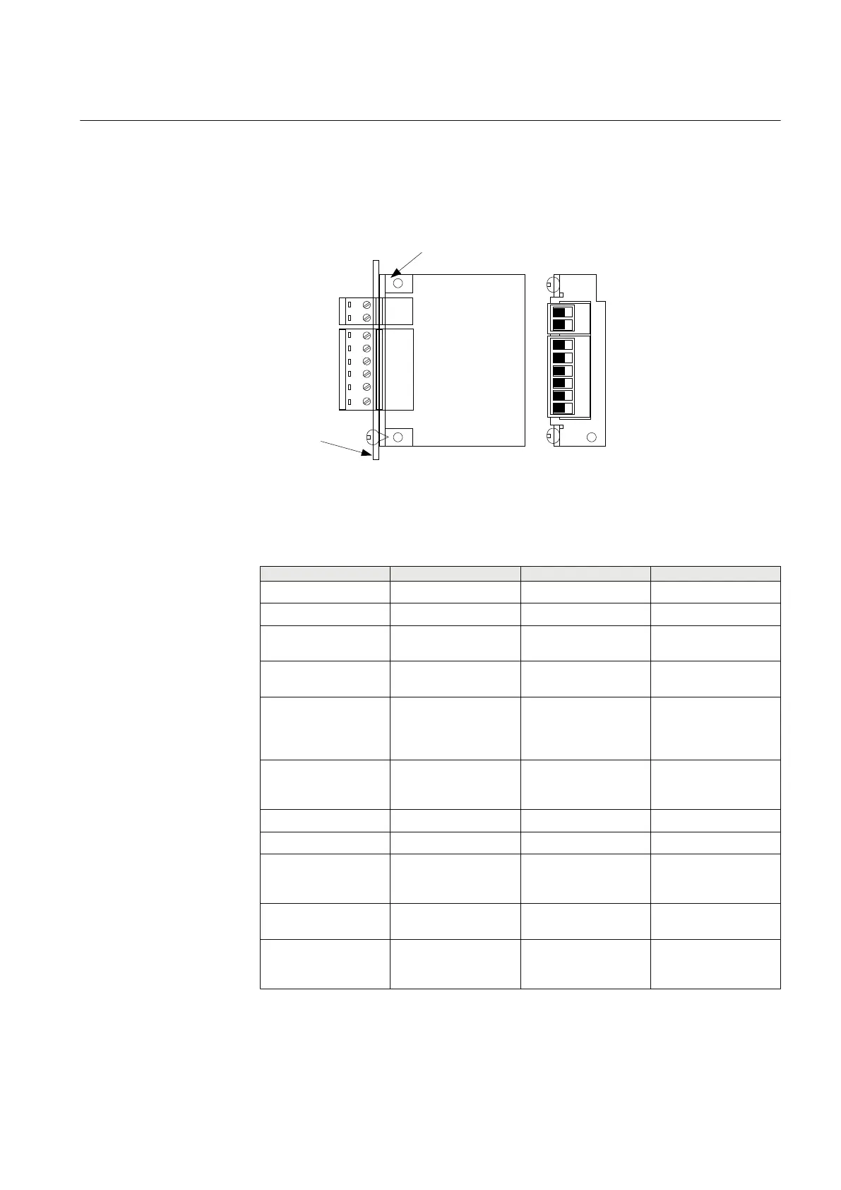
RS485 serial communication module
RS485
P
WB
Screw
te
rminal
X1
Backplate
Screw
te
rminal
X3
Angle
bracket
1
2
4
5
6
3
1
2
en07000140.vsd
IEC07000140 V1 EN
Figure 35: The connection plate to the backplate with connectors and screws.
This figure also shows the pin numbering from the component side
Pin Name 2-wire Name 4-wire Description
x3:1 soft ground
x3:2 soft ground
x1:1 RS485 + TX+ Receive/transmit high
or transmit high
x1:2 RS485 – TX- Receive/transmit low
or transmit low
x1:3 Term T-Term Termination resistor
for transmitter (and
receiver in 2-wire
case) (connect to TX+)
x1:4 reserved R-Term Termination resistor
for receiver (connect to
RX+)
x1:5 reserved RX- Receive low
x1:6 reserved RX+ Receive high
2–wire: Connect pin X1:1 to
pin X1:6 and pin X1:2
to pin X1:5.
Termination (2-wire): Connect pin X1:1 to
pin X1:3
Termination (4-wire): Connect pin X1:1 to
pin X1:3 and pin X1:4
to pin X1:6
1MRK 504 088-UEN C Section 5
Installing the IED
65
Installation and commissioning manual

 Loading...


