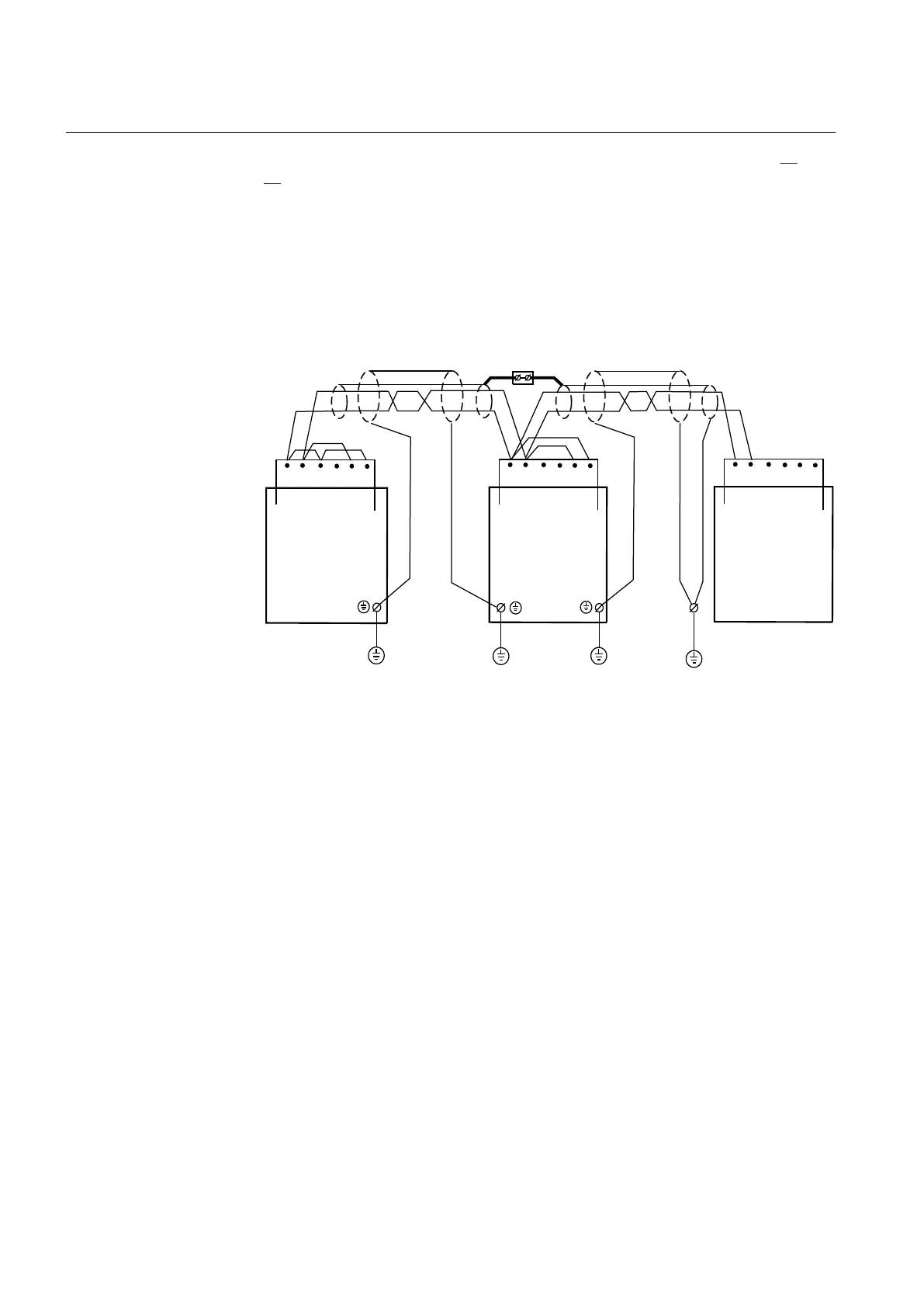
The distance between earth points should be < 1200 m (3000 ft), see figure 36 and
37. Only the outer shielding is connected to the protective earth at the IED. The
inner and outer shieldings are connected to the protective earth at the external
equipment. Use insulating tape for the inner shield to prevent contact with the
protective earth. Make sure that the terminals are properly earthed with as short
connections as possible from the earth screw, for example to an earthed frame.
The IED and the external equipment should preferably be connected to the same
battery.
en07000141.vsd
Cc
Cc
1)
External
Equipment (PC)
PE 1) 3)
2)
PE
IED
X1
1 65432
IED
1 65432
X1
PE
PE
IEC07000141 V1 EN
Figure 36: Communication cable installation, 2-wire
Where:
1 The inner shields shall be connected together (with an isolated terminal block) and only
have one earthing point in the whole system, preferably at the external equipment (PC).
The outer shield shall be connected to Protective
Earth (PE) in every cable end that is, to PE
at all IED terminals and to PE at External equipment (PC). The first IED will have only one
cable end but all others of course two.
2 Connect according to installation instructions for the actual equipment, observe the 120
ohms termination.
3 The protective earth should be close to the external equipment (< 2m)
Cc Communication cable
PE Protective earth screw
Section 5 1MRK 504 088-UEN C
Installing the IED
66
Installation and commissioning manual

 Loading...


