en07000142.vsd
External
Equipment (PC)
PE 1) 3)
2)
IED
1 65432
X1
PE
PE
Cc
PE
IED
X1
1 65432
1)
1)
Cc
IEC07000142 V1 EN
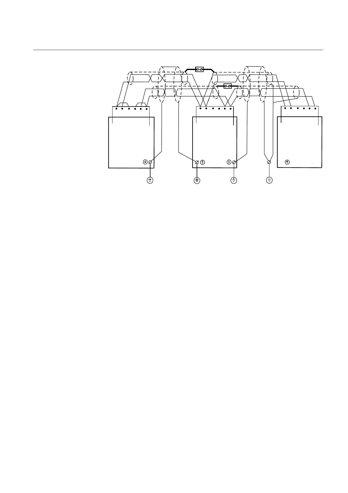
Figure 37: Communication cable installation, 4-wire
Where:
1 The inner shields shall be connected together (with an isolated terminal block) and only
have one earthing point in the whole system, preferably at the external equipment (PC).
The outer shield shall be connected to Protective
Earth (PE) in every cable end that is, to PE
at all IED terminals and to PE at External equipment (PC). The first IED will have only one
cable end but all others of course two.
2 Connect according to installation instructions for the actual equipment, observe the 120
ohms termination.
3 The protective earth should be close to the external equipment (< 2m)
Cc Communication cable
PE Protective earthscrew
1MRK 504 088-UEN C Section 5
Installing the IED
67
Installation and commissioning manual

 Loading...


