8 Connection made in the Signal Matrix, which connects this current input to first input channel
of the preprocessing function block (10). For high impedance differential protection
preprocessing function block in 3ms task shall be used.
9 Preprocessing block, which has a task to digitally filter the connected analogue inputs.
Preprocessing block output AI1 shall be connected to one instances of 1Ph high impedance
differential protection function HZPDIF (for example, instance 1 of HZPDIF in the configuration
tool).
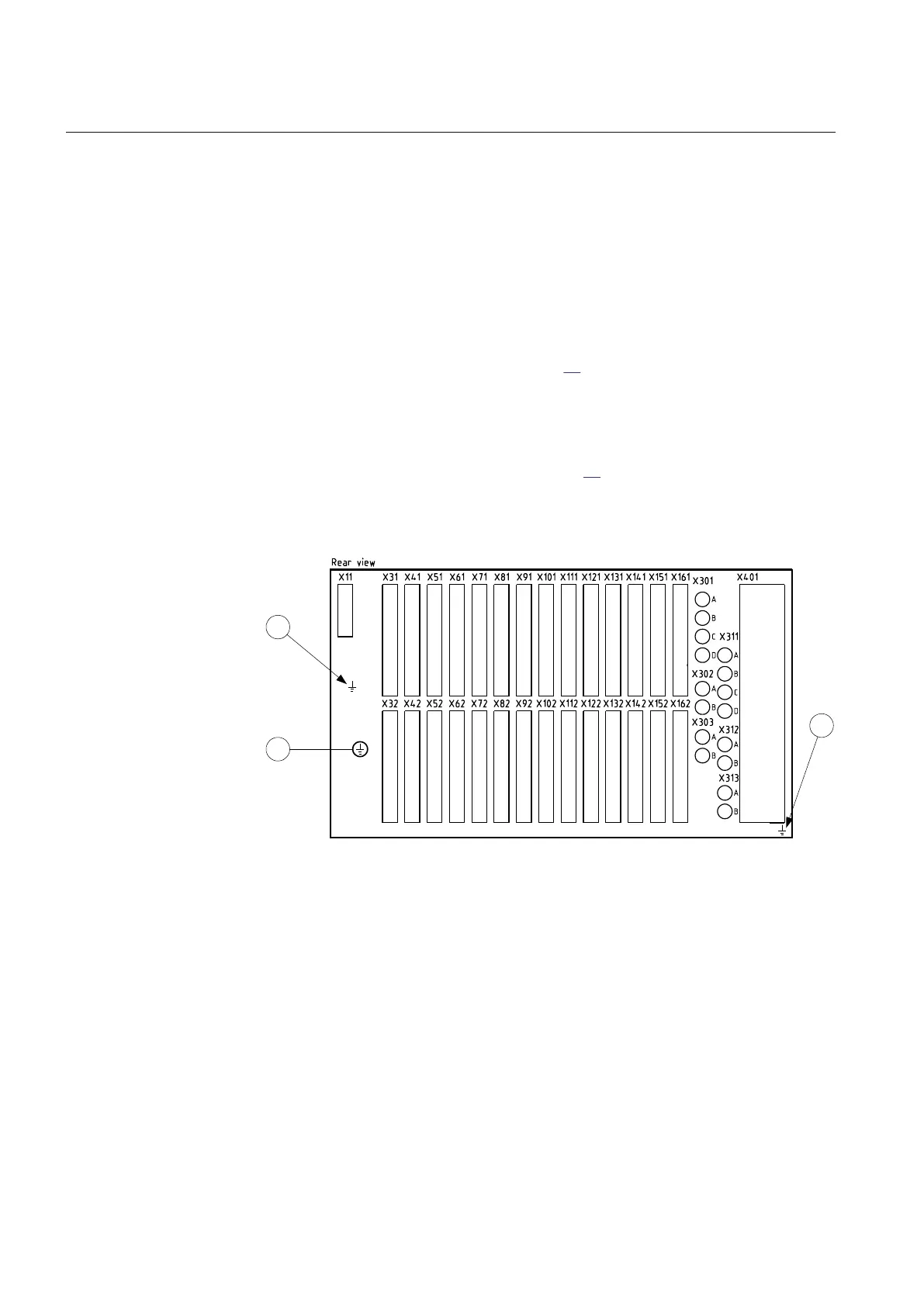
5.4.2 Connecting to protective earth
Connect the earthing
screw (pos 1 in figure
30) on the rear of the IED to the closest
possible earthing point in the cubicle. Electrical codes and standards require that
protective earth
cables are green/yellow conductors with a cross section area of at
least 2.5 mm
2
(AWG14). There are several protective earthing screws on an IED.
The Power supply module (PSM), Transformer input modules (TRM) and the
enclosure are all separately earthed, see figure
30 below.
The cubicle must be properly connected to the station
earthing system. Use a
conductor with a core cross section area of at least 4 mm
2
(AWG 12).
IEC05000509 V1 EN
Figure 30: Rear view of IED showing earthing points.
Pos Description
1 Main protective earth to chassis
2 Earthing screw to Power supply module (PSM)
3 Earthing screw to Transformer input module (TRM). (There is one
earth connection per TRM)
Section 5 1MRK 504 088-UEN C
Installing the IED
58
Installation and commissioning manual

 Loading...


