5.4.1.4 Connection examples
WARNING! USE EXTREME CAUTION! Dangerously high
voltages might be present on this equipment, especially on the plate
with resistors. Do any maintenance ONLY if the primary object
protected with this equipment is de-energized. If required by
national law or standard, enclose the plate with resistors with a
protective cover or in a separate box.
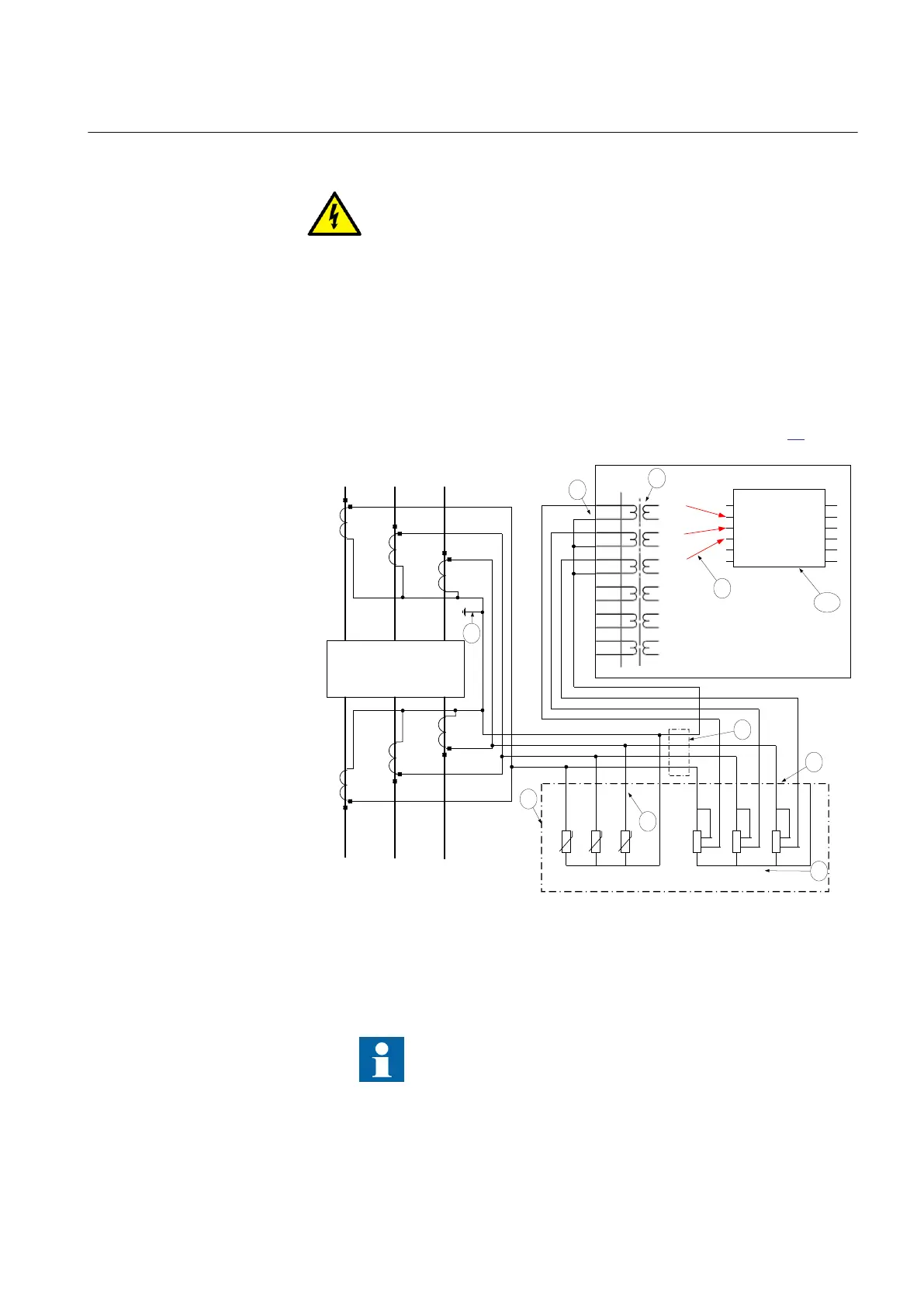
Connections for three-phase high impedance differential protection
Generator,
reactor or busbar differential protection is a typical application for three-
phase high impedance differential protection. Typical CT connections for three-
phase high impedance differential protection scheme are shown in figure
28.
L1
(A)
L2
(B)
L3
(C)
Protected Object
CT 1200/1
Star/Wye
Connected
L1
(A)
L2
(B)
L3
(C)
CT 1200/1
Star/Wye
Connected
7
8
9
1
0
1
1
1
2
1
2
3
4
5
6
AI01
(I)
AI02
(I)
AI03
(I)
AI04
(I)
AI05
(I)
AI06
(I)
7
8
6
9
X1
R
4
R
5
R
6
1
2
1
2
1
2
11 12 13 14
U
U
U
R
1
1
3
4
2
1
3
R
2
2
4
1
3
R
3
2
4
1 2 3 4 5 6 7
L1 (A)
L2 (B)
L3 (C)
N
3-Ph Plate with Metrosils and Resistors
2
3
5
4
10
X X
L1 (A)
L2 (B)
L3 (C)
N
1
IED
IEC07000193_2_en.vsd
AI3P
AI1
AI2
AI3
AI4
AIN
SMAI2
BLOCK
^GRP2L1
^GRP2L2
^GRP2L3
^GRP2N
TYPE
IEC07000193 V2 EN
Figure 28: CT connections for high impedance differential protection
Pos Description
1 Scheme earthing point
Note that it is of outmost importance to insure that only one earthing point
exist in such scheme.
2 Three-phase plate with setting resistors and metrosils.
1MRK 504 088-UEN C Section 5
Installing the IED
55
Installation and commissioning manual

 Loading...


