EasyManuals Logo

ABB RET670 Installation And Commissioning Manual

ABB RET670
240 pages
To Next Page IconTo Next Page
To Previous Page IconTo Previous Page
Page #51 background imageLoading...
Page #51 background image
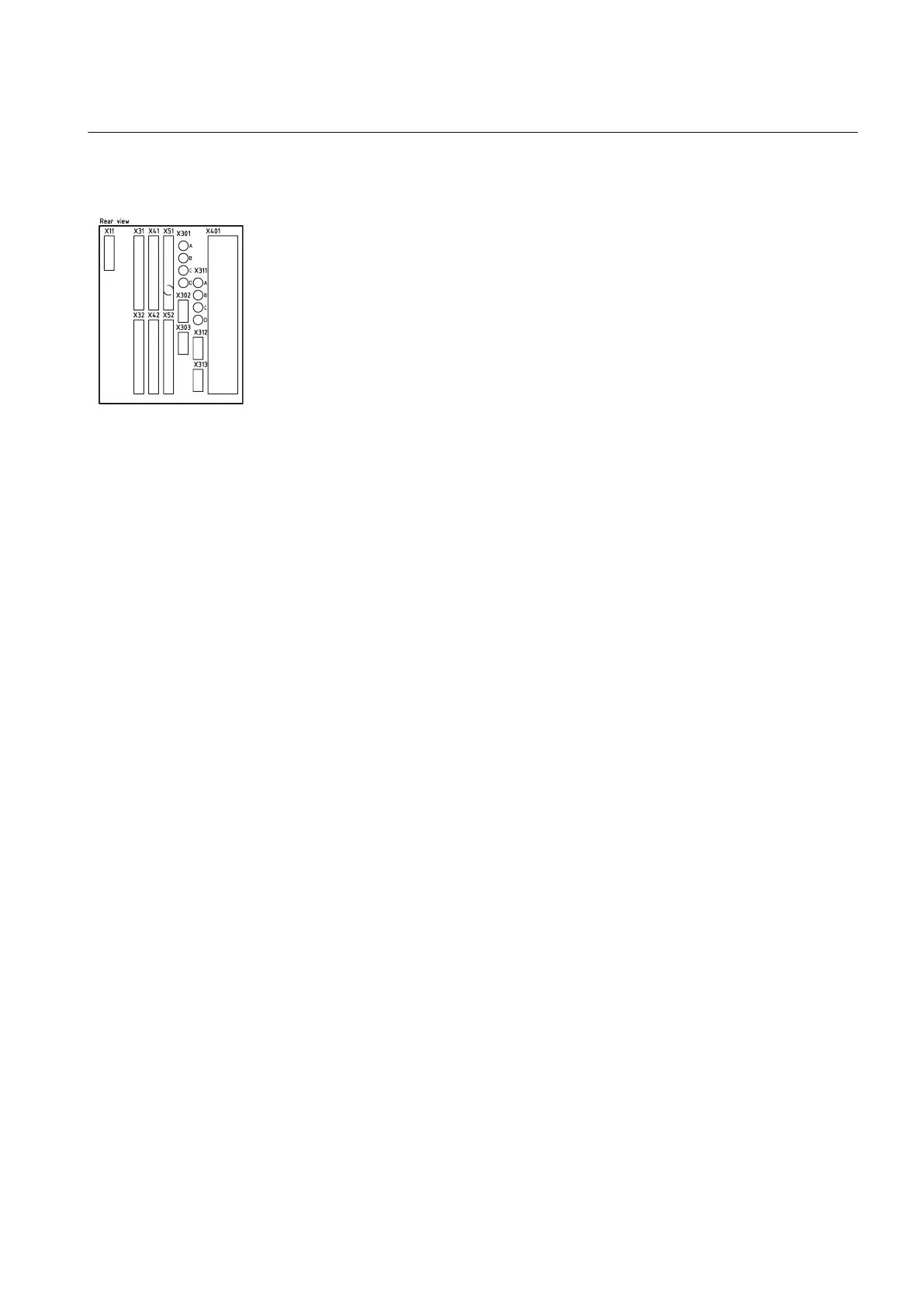
5.4.1.3 Rear side connectors
Table 3: Designations for 1/2 x 19” casing with 1 TRM slot
IEC08000471 BG V1 EN
Module Rear Positions
PSM X11
BIM, BOM, SOM or IOM X31 and X32 etc. to X51
and X52
BIM, BOM, SOM, IOM or
GSM
X51, X52
SLM X301:A, B, C, D
IRIG-B 1) X302
OEM X311:A, B, C, D
RS485 or LDCM 2) 3) X312
LDCM 2) X313
TRM X401
1) IRIG-B installation, when included in seat P30:2
2) LDCM installation sequence: P31:2 or P31:3
3) RS485 installation, when included in seat P31:2
Note!
1 One LDCM can be included depending of availability of
IRIG-B respective RS485 modules.
1MRK 504 088-UEN C Section 5
Installing the IED
45
Installation and commissioning manual

Table of Contents

Other manuals for ABB RET670

Questions and Answers:

Question and Answer IconNeed help?

Do you have a question about the ABB RET670 and is the answer not in the manual?

ABB RET670 Specifications

General IconGeneral
Rated Frequency50/60 Hz
InputsAnalog and binary inputs
ApplicationProtection of power systems
Communication ProtocolsIEC 61850, DNP3, Modbus
Operating Temperature Range-25°C to +55°C
MountingRack mounted
Number of Binary InputsUp to 48
Number of Binary Outputs32
Protection FunctionsOvercurrent Protection
OutputsBinary outputs
EnclosureIP 54
TypeLine Differential Protection
Number of Analog Inputs24

Related product manuals