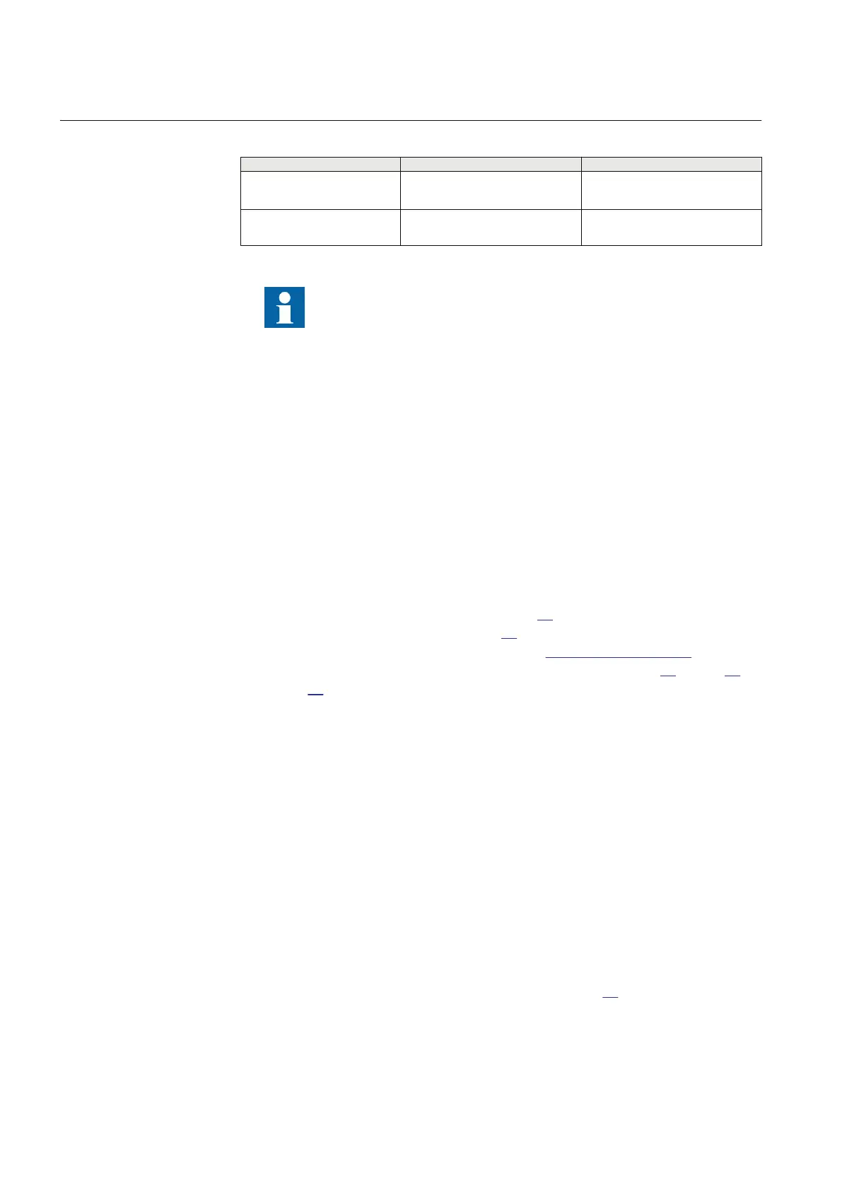
Table 9: Binary I/O connection system
Connector type Rated voltage Maximum conductor area
Screw compression type 250 V AC
2.5 mm
2
2 × 1 mm
2
Terminal blocks suitable for
ring lug terminals
300 V AC
3 mm
2
Because of limitations of space, when ring lug terminal is ordered
for Binary I/O connections, one blank slot is necessary between two
adjacent
IO cards. Please refer to the ordering particulars for details.
5.4.4.1 Configuration for analog CT inputs
The secondary rated current of the CT (that is, 1A or 5A) determines the choice of
TRM in the IED. Two TRMs are available, One is dimensioned for an input current
of 5A and the other for an input of 1A. If the CT rated secondary current does not
match the TRM input current rating adjustments can be made in settings depending
on the tolerance of the TRM.
5.4.5
Connecting the binary input and output signals
Auxiliary power and signals are connected using voltage connectors. Signal wires
are connected to a female connector, see figure
31, which is then plugged into the
corresponding male connector, see figure 32, located at the rear of the IED. For
location of BIM, BOM and IOM refer to section "Rear side connectors".
Connection diagrams for BIM, BOM and IOM are shown in figure 20, figure 25
and figure 27.
If the IED is equipped with a test-switch of type RTXP 24 COMBIFLEX wires
with 20 A sockets, 1.5mm² (AWG16) conductor area must be used to connect the
auxiliary power.
Procedure
1.
Connect signals to the female connector
All wiring to the female connector should be done before it is plugged into
the male part and screwed to the case. The conductors can be of rigid type
(solid, stranded) or of flexible type.
The female connectors accept conductors with a cross section area of 0.2-2.5
mm
2
(AWG 24-14). If two conductors are used in the same terminal, the
maximum permissible cross section area is 0.2-1 mm
2
(AWG 24-18).
If two conductors, each with area 1.5 mm
2
(AWG 16) need to be connected to
the same terminal, a ferrule must be used, see figure
33. This ferrule, is
applied with the by Phoenix recommended crimping tool. No soldering is
needed. Wires with a smaller gauge can be inserted directly into the female
Section 5 1MRK 504 088-UEN C
Installing the IED
60
Installation and commissioning manual

 Loading...


