Set value:
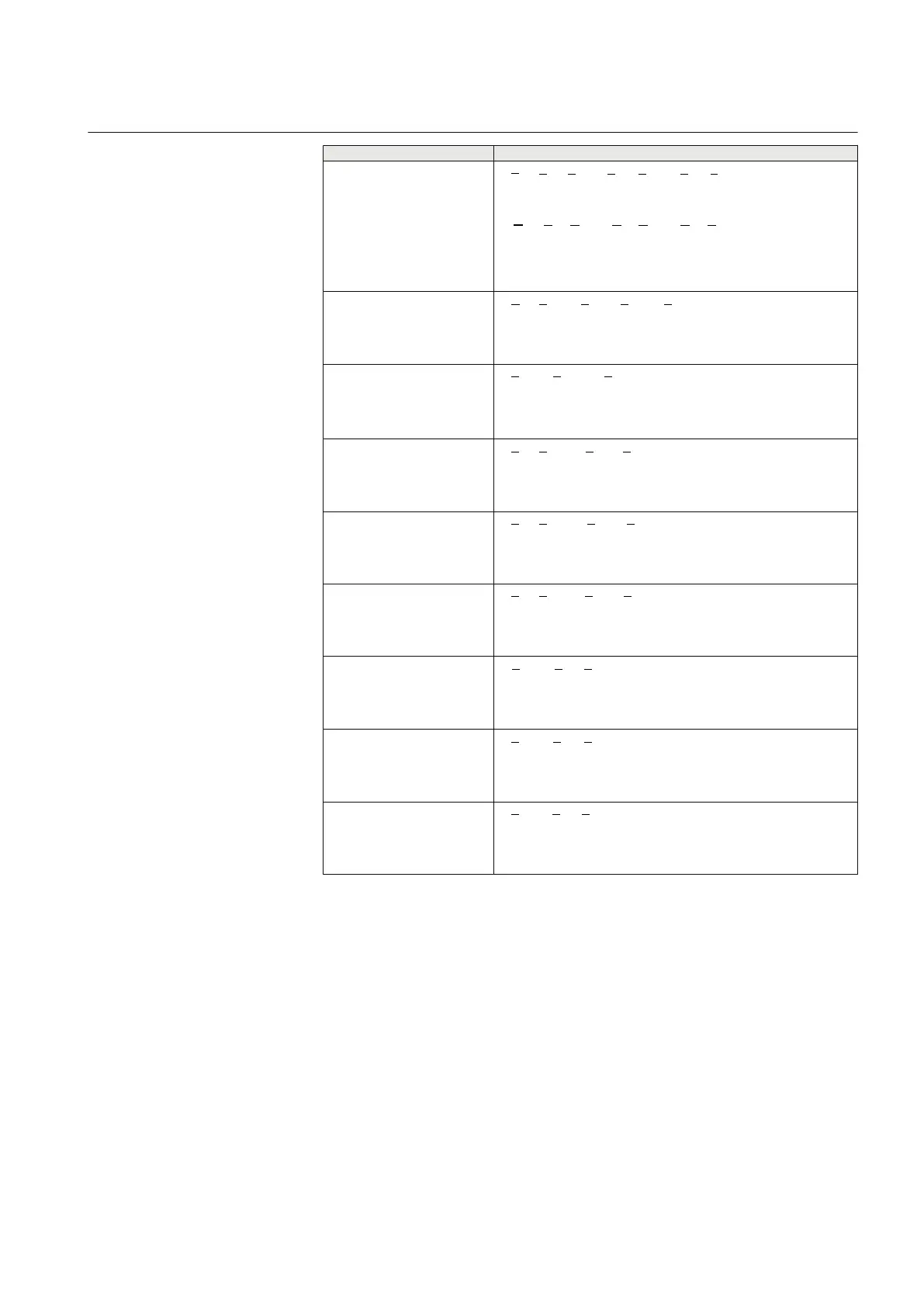
Mode
Formula used for complex power calculation
L1, L2, L3
* * *
1 1 2 2 3 3L L L L L L
S U I U I U I= × + × + ×
EQUATION1697 V1 EN (Equation 4)
* * *
A A B B C C
S V I V I V I= × + × + ×
EQUATION2055 V1 EN (Equation 4)
Arone
* *
1 2 1 2 3 3L L L L L L
S U I U I= × - ×
EQUATION1698 V1 EN (Equation 5)
PosSeq
*
3
PosSeq PosSeq
S U I= × ×
EQUATION1699 V1 EN (Equation 6)
L1L2
* *
1 2 1 2
( )
L L L L
S U I I= × -
EQUATION1700 V1 EN (Equation 7)
L2L3
* *
2 3 2 3
( )
L L L L
S U I I= × -
EQUATION1701 V1 EN (Equation 8)
L3L1
* *
3 1 3 1
( )
L L L L
S U I I= × -
EQUATION1702 V1 EN (Equation 9)
L1
EQUATION1703 V1 EN (Equation 10)
L2
EQUATION1704 V1 EN (Equation 11)
L3
EQUATION1705 V1 EN (Equation 12)
2. Adjust the injected current and voltage to the set values in % of IBase and
UBase (converted to secondary current and voltage). The angle between the
injected current and voltage shall be set equal to the set direction Angle1,
angle for stage 1 (equal to 0° for low forward power protection and equal to
180° for reverse power protection). Check that the monitored active power is
equal to 100% of rated power and that the reactive power is equal to 0% of
rated power.
3.
Change the angle between the injected current and voltage to Angle1 + 90°.
Check that the monitored active power is equal to 0% of rated power and that
the reactive power is equal to 100% of rated power.
4. Change the angle between the injected current and voltage back to 0°.
Decrease the current slowly until the START1 signal, start of stage 1, is
activated.
1MRK 504 088-UEN C Section 13
Verifying settings by secondary injection
153
Installation and commissioning manual

 Loading...


