1 Normative references
EIA Standard RS-485 - Electrical Characteristics of Generators and Receivers for Balanced Digital
Multipoint Systems
2 Transmission method
RS-485 differential bipolar signaling
2.1 Differential signal levels
Two differential signal levels are defined:
A+ =line A positive with respect to line B
A- =line A negative with respect to line B
2.2 Galvanic isolation
The RS485 circuit shall be isolated from earth by:
Riso ≥ 10 MW
Ciso ≤ 10 pF
Three isolation options exist:
a) The entire node electronics can be galvanically isolated
b) The bus interface circuit can be isolated form the rest of node electronics by
optoisolators, transformer coupling or otherwise.
c) The RS485 chip can include built-in isolation
2.3 Bus excitation and signal conveyance
2.3.1 Requirements
a) The RS485 specification requires the Signal A and Signal B wires.
b) Each node also requires (5 V) Excitation of the RS485 termination network.
c) Vim - the common mode voltage between any pair of RS485 chips may not exceed 10 V.
d) A physical ground connection between all RS485 circuits will reduce noise.
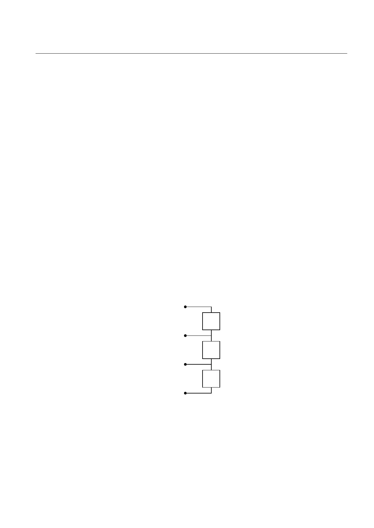
2.3.2 Bus segment termination network
The termination network below required at each end of each Bus Ph-segment.
en03000112.vsd
ExV+
Signal B
Signal A
DGND
Ru = 390 ohm
1/4 W, 2%
Rt = 220 ohm
1/4 W, 2%
Rd = 390 ohm
1/4 W, 2%
ExV is supplied by the Node at end of the Bus Segment
IEC03000112 V1 EN
Figure 40: RS-485 bus segment termination
Table continues on next page
1MRK 504 088-UEN C Section 5
Installing the IED
69
Installation and commissioning manual

 Loading...


