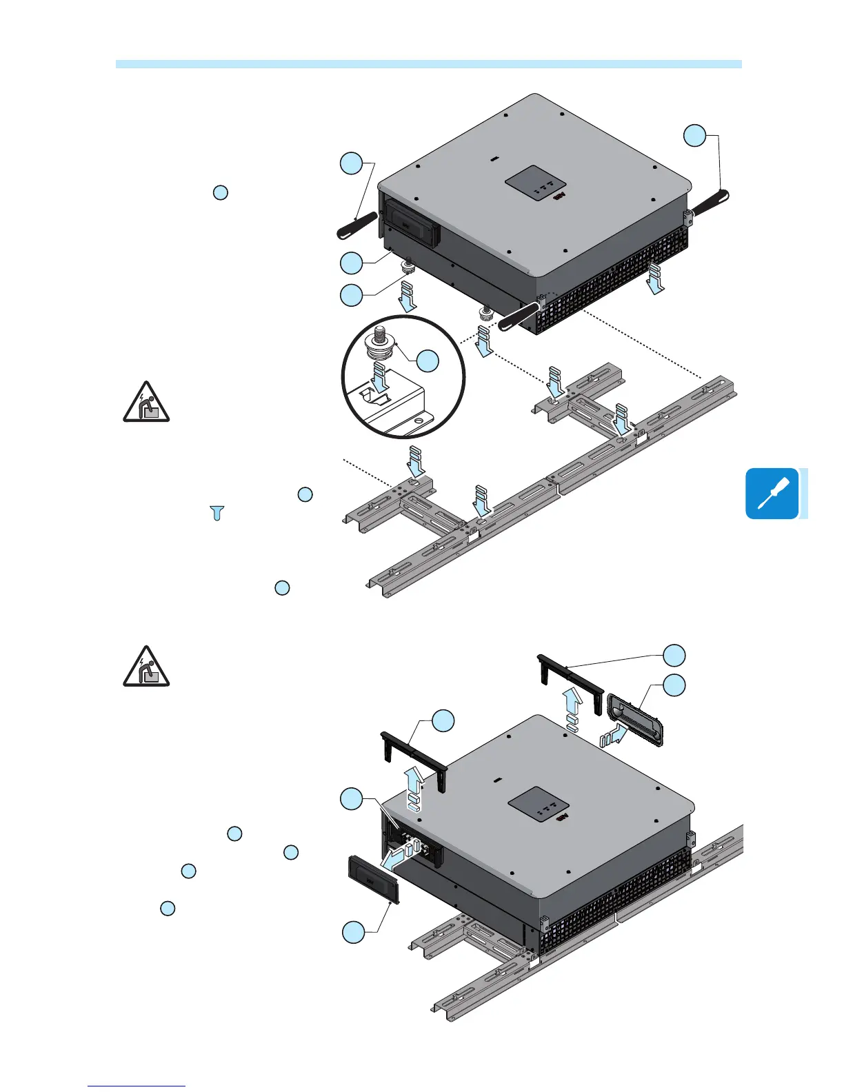
• Lift the power module up to
the bracket using the (optio-
nal) handles
06
or the (op-
tional) M12 eyebolts, or ano-
ther appropriate lifting device.
The power module is pre-equip-
ped with metal expansions which
allow it to be temporarily put ver-
tically on the oor to make it ea-
sier the installation of handles or
eyebolts.
Risk of injury due to
the heavy weight of
the equipment.
• Insert the heads of two up-
per rear attachment pins
27
into the slots on the bracket
positioning the power modu-
le at the center of the bracket.
Check that all 4 rear pins
27
are
correctly inserted into the slots.
Risk of injury due to
the heavy weight of
the equipment.
• Remove handle or eye bolts (if
used)
• Remove the quick disconnect
connector covers
04
as follows:
- Pull the metal locking fork
07
outwards
A
- Pull off the quick disconnect
cover
B
Save both parts. They will be
needed in a later step.
04
04
06
03
27
06
27
07
23
07

 Loading...