3 +T/R
5 -T/R
7 RTN
1, 2, 4, 6, 8 not used
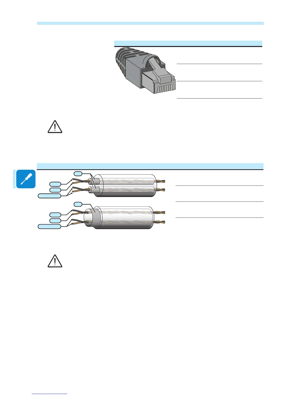
Use a connector with metal body to provide cable shield continuity!
For long distance connections, the connection on terminal connector
is preferable using a shielded twisted pair cable with characteristic
impedance of Z0=120 Ohm like the one shown on the following table:
Signal Symbol
-T/R
+T/R
SH
GND COM
-T/R
+T/R
SH
GND COM
Positive data +T/R
Negative data -T/R
Reference RTN
Screen SH
Shield continuity must be provided along the communication line using the SH terminal and
must be grounded at a single point.

 Loading...