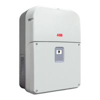
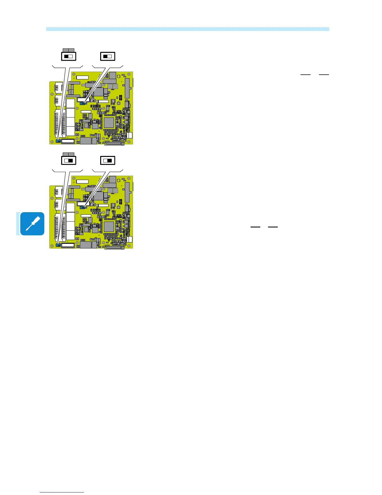
When connecting a single inverter to the monitoring system, activate the
communication line resistance terminal by setting the switch a12 or a13
(to the ON position).
Set a different RS485 address on each inverter in the chain. No inverter
can have “Auto” as an address. An address can be freely chosen
between 2 and 63.
The setting of the address on the inverter is done through the "Aurora
Manager" software.
When an RS-485 connection is being used, if one or more inverters are
added to the system at a later time, it is necessary to remember to reset
to OFF the switch on the termination resistance being used (1) or (2) on
the inverter which previously was the last in the system.
Each inverter is shipped with the RS485 address pre-set to two (2) and
with the resistance terminal setting Switch a12 or a13 in the OFF position.
PC2
ON
3
2
1
OFF
S5
S6
ON
3
2
1
OFFPC1
R46
R49
S7
3
2
1
J1
J18
J7 J5
J8
X5
2
2
1
1
18
17
J6
J15
J15
J16

 Loading...