12
AcuRev 1300
2.3 Wiring
Terminals:
This manual use L1 L2 L3 to represent three-phase current loop, which are the same as
A, B, C in other manuals.
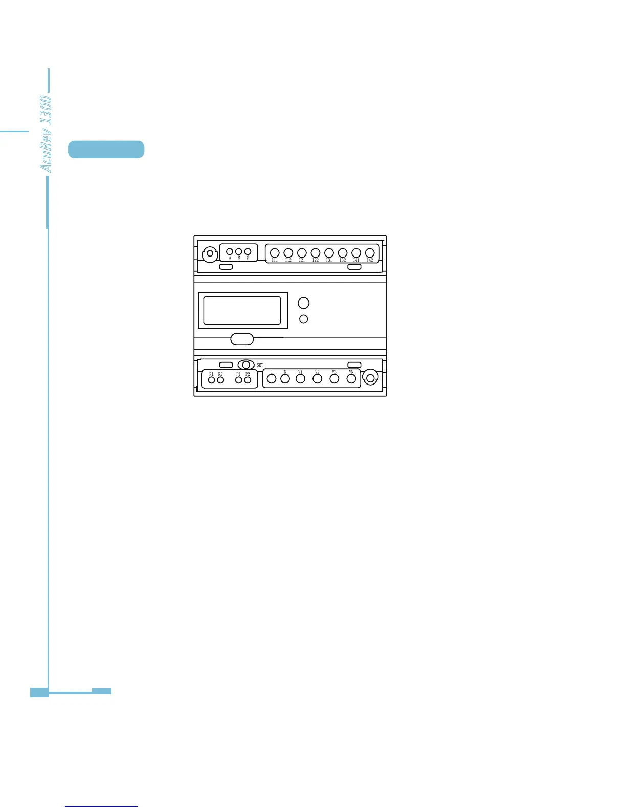
Figure 2-8 The transformer AcuRev1300 terminal access type distribution
A, B, S: communications terminal; P1, P2: pulse output;
L, N: auxiliary power; V1, V2, V3 and.Vn: voltage circuit; I11, I12, I21 I22, I31, I32, I41, I42:
current loop; R1, R2: RO output.
AuxiliaryPower Supply:
AcuRev1300 series instrument power supply: ac 100 ~ 415 vac, 50/60 hz, or dc 100-
300 VDC, can be used throughout the world. Other power supply voltage selection
please contact manufacturers. Instrument in the typical working conditions of power
consumption is very small, so the power supply can by independent power supply, can also
be obtained from circuit under test.Suggested that under the condition of power voltage
uctuation is bigger, use the voltagee stabilizer. Power supply terminals, respectively is: L, N.
The typical auxiliary power wiring is as follows:

 Loading...


