EasyManua.ls Logo

ACT apricot - Page 139

ACT apricot
328 pages
Print Icon
To Next Page IconTo Next Page
To Previous Page IconTo Previous Page
Loading...
SERIAL INTERFACE
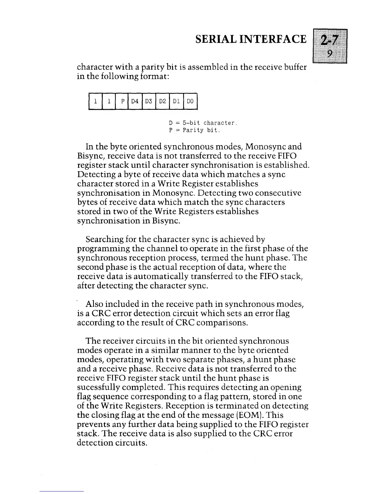
character
with
a
parity
bit
is
assembled
in
the
receive buffer
in
the
following format:
11
11
1 P 1
D41
D31
D21
D1
1
DO
I
D =
5-bit
character.
P =
Pari
ty
bit.
In
the
byte
oriented
synchronous
modes,
Monosync
and
Bisync, receive
data
is
not
transferred
to
the
receive FIFO
register
stack
until
character
synchronisation
is established.
Detecting
a
byte
of receive
data
which
matches
a
sync
character
stored
in
a
Write
Register
establishes
synchronisation
in
Monosync.
Detecting
two
consecutive
bytes
of receive
data
which
match
the
sync
characters
stored
in
two
of
the
Write
Registers
establishes
synchronisation
in
Bisync.
Searching for
the
character
sync
is
achieved
by
programming
the
channel
to
operate
in
the
first
phase
of
the
synchronous
reception
process,
termed
the
hunt
phase.
The
second
phase
is
the
actual
reception
of data,
where
the
receive
data
is
automatically
transferred
to
the
FIFO stack,
after
detecting
the
character
sync.
- Also
included
in
the
receive
path
in
synchronous
modes,
is a
eRe
error
detection
circuit
which
sets
an
error flag
according
to
the
result
of
eRe
comparisons.
The
receiver
circuits
in
the
bit
oriented
synchronous
modes
operate
in
a
similar
manner
to.
the
byte
oriented
modes,
operating
with
two
separate
phases, a
hunt
phase
and
a receive phase. Receive
data
is
not
transferred
to
the
receive FIFO
register
stack
until
the
hunt
phase
is
sucessfully
completed.
This
requires
detecting
an
opening
flag
sequence
corresponding
to
a flag
pattern,
stored
in
one
of
the
Write
Registers.
Reception
is
terminated
on
detecting
the
closing flag
at
the
end
of
the
message
(EOM).
This
prevents
any
further
data
being
supplied
to
the
FIFO register
stack.
The
receive
data
is
also
supplied
to
the
eRe
error
detection
circuits.

Table of Contents

Other manuals for ACT apricot