CRT
CONTROL
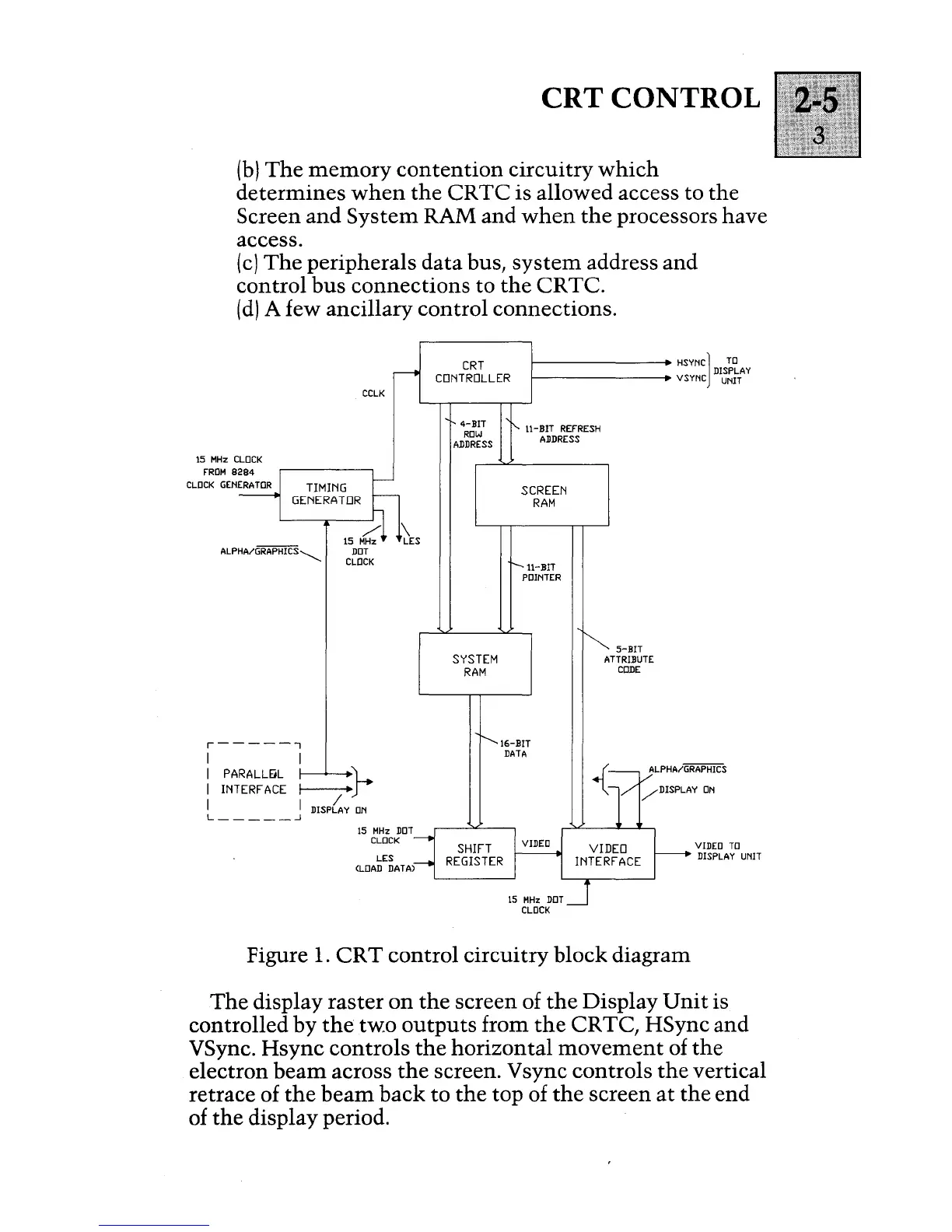
(b)
The memory contention circuitry
which
determines
when
the CRTC is allowed access to the
Screen and System RAM and
when
the processors have
access.
(c)
The peripherals data bus,
system
address and
control bus connections to the CR TC.
(d)
A few ancillary control connections.
15
MHz
CLOCK
FROM
8284
ALPHA/GRAPHICS~
r-----,
I I
CCLK
I
PARALLEiL
L
I
INTERFACE
~;--
I I
DISP6.
Y
ON
L
_____
...l
15
MHz
DDT
CLOCK
LES
(LOAD DATA)
DISPLAY
CRT
CONTROLLER
HSYNC]
TO
1--------
VSYNC UNIT
4-BIT
ROW
ADDRESS
SYSTEM
RAM
11-
BIT
REFRESH
ADDRESS
SCREEN
RAM
ll-BIT
POINTER
16-BIT
DATA
5-BIT
ATTRIBUTE
CODE
VIDEO
TO
DISPLAY UNIT
Figure
1.
CRT control circuitry block diagram
The display raster
on
the screen of the Display
Unit
is
controlled by the
two
outputs from the CR
TC
,
HSync and
VSync. Hsync controls the horizontal
movement
of the
electron beam across the screen. Vsync controls the vertical
retrace of the beam back to the top of the screen at the end
of the display period.


 To Next Page