!"##"$"%"&%*""#
XM_unity_Installation&Maintenance_Manual Ed.1.3c2013 Page ;5of (()
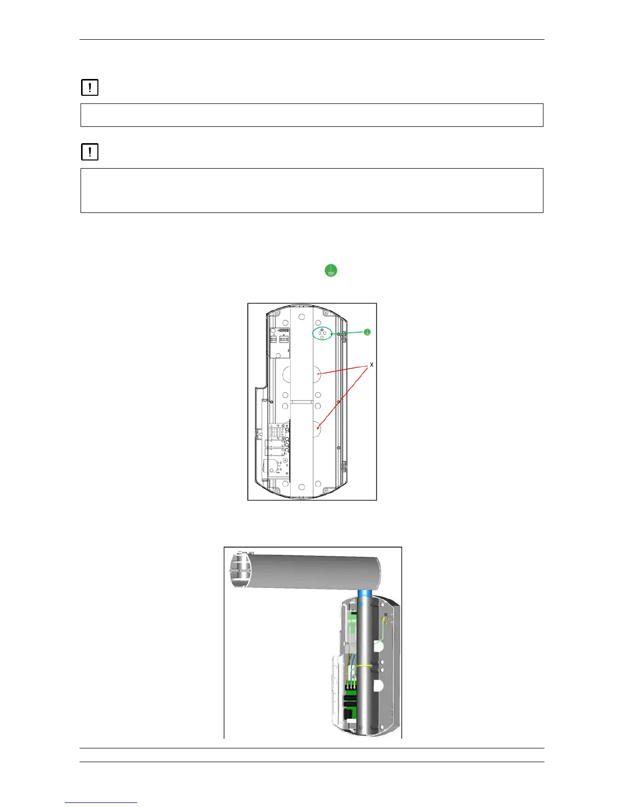
Fig. 5.9
3%"!!%*8#H3%*%&3"&"#-"0!*"F%!0%3"$&"8#%!"0%-&3%/8%1%%-"0!$0-$!$3%*$0/%0
3"3% &"M8%/"*"H%/" 1" 4
$$H3$$*&33%&"8#%!4$$-$!$3%*"!0%!!%/-$!$4
According to the configuration (TOP or BOTTOM), all the cables coming from the bracket must exit from the topright holes DE as
shown in Fig. 5.10 5.11.
Ground and shielded cables must be connected to the ground point by means of the dedicated screws and rings preinstalled
on the wall plate.
Fig. 5.10
Bracket correctly installed (example of Top Installation. The same approach, but inverted, is also valid for the bottom configuration)