!"##"$"%"&%*""#
Page '@of (()XM_unity_Installation&Maintenance_Manual Ed.1.3c2013
54=4
The electrical system must be suitably earthed, in compliance with IEC and American NEC standards and with the laws in force in
the country of installation.
In Italy, the system must be made in a workmanlike manner and in compliance with the CEI 648 standard, including all collateral
standards concerning premises dedicated for medical purposes
XRay control unit (Timer)
On the timer installation wall, suitable runs for the following electric cables must be provided, according to the installation electric
diagram:
XRay control unit (Timer) mains cables
Cables connecting the timer and the XRay signalling lamp #H3 (optional) (20 AWG, CSA/UL/IEC)
Cables connecting the timer and the 0%*$%&$0$# button (optional) (24 AWG, CSA/UL/IEC)
""
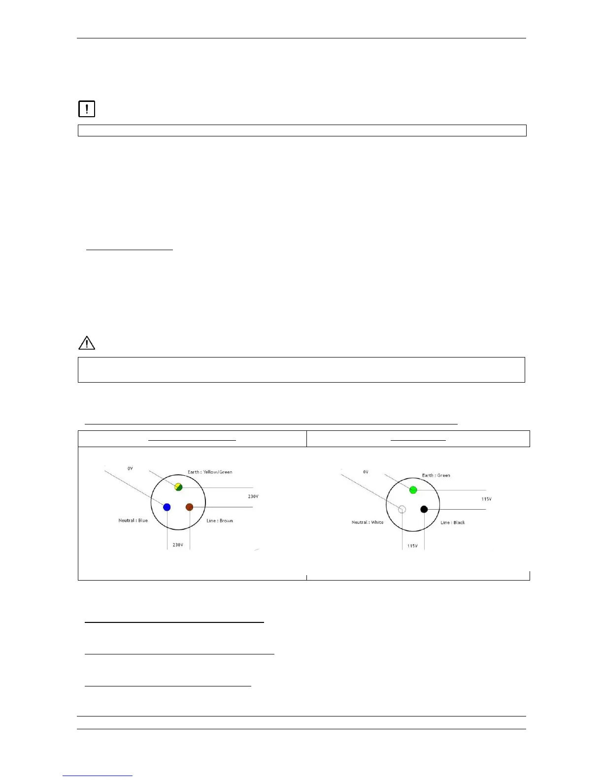
The connecting cables between the mains and the timer must be run through the wall supporting the wall plate:
EU Line (brown): 16 AWG / US Line (black): 16 AWG
EU Ground (yellow/green) / US Ground (green) 16 AWG
EU Neutral (blue): 16 AWG / US (white): 16 AWG