!"##"$"%"&%*""#
Page ';of (()XM_unity_Installation&Maintenance_Manual Ed.1.3c2013
54'4
The supporting wall where the XMIND unity is installed must be able to stand ;;BHDABC4@CE tear at every fixing point.
Select the right type of wall anchors basing on the wall type, they also should be identical for every attachment point and always
complying with the force value reported above.
"80&F1$0F%6-%04
$M!"##3%$1"##!13&%0"&$!!%& $0*"/%13*"%0"#3"!$"8#%$!--$03%1%H3!"/
3%!-%&.&"$!/%!&08%/3%"&&$*-" H/$&*%!$.3% 4
5454
The electrical system must comply with the regulations in force.
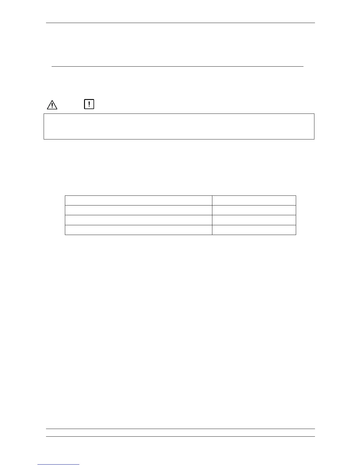
The electrical system must be able to supply the power and voltage required in the manufacturer’s rating plate of the radiographic
system (chart A)
Chart A
54;4
The electric line must be “single phase alternating” type with range 100 240 VAC.
The electric line must be dedicated to the power supply of the XMIND unity system.
The electrical wiring must be effectively grounded complying to IEC US NATIONAL ELECTRICAL CODE AND CEI Standards
or in any case, all local standards.
It is essential install a 16A – 250V breaker/differential (Id ≤ 0.03A) switch upstream the radiographic system mains, however it is
MANDATORY verifying and complying to current local standards.
On the power supply line must be installed a mains switch, able to isolate the equipment from the supply mains.
The power cord to be used for the power supply of the XMIND unity should be TWOPOLE+GROUND type, section minimum 1.5
mm
2
716AWG (3G1.5), 300/500 V, CSA/UL IEC
The power cord used must also conform to the eventual additional regulations of the country of installation.
No other equipment should be connected to the same fused mains line as the XMIND unity.
Basing on the length of the power supply line: See (Chart B)