Spur / Backbone
Topologies are
Unsupported
Star Topologies are
Unsupported
ECLYPSE ECLYPSE
Figure107: Unsupported Modbus RTU Data Bus Topologies
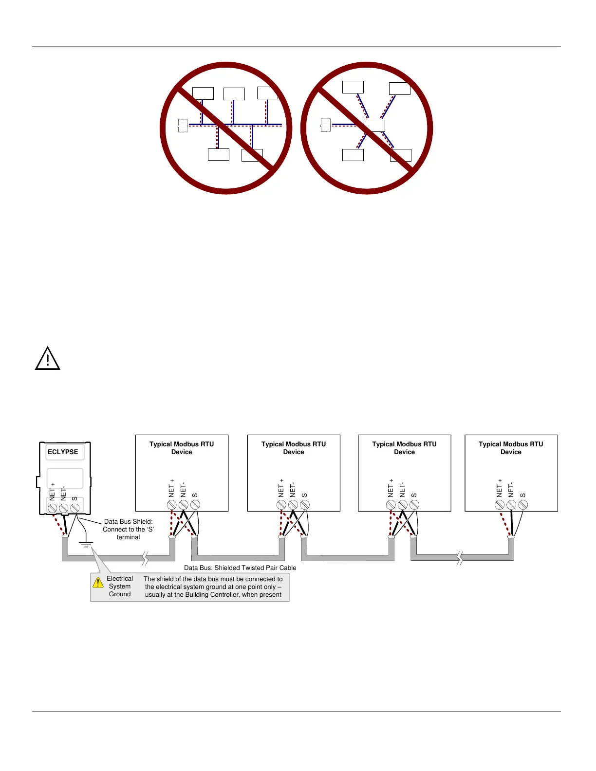
Data Bus Shield Grounding Requirements
The EIA-485 data bus standard requires that the data bus must be shielded against interference. A Modbus RTU data bus
must also be properly grounded.
The data bus’ cable shields must be twisted together and connected to the S or shield terminal at each ECLYPSE Con-
troller. Keep the cable shield connections short and take steps at each device to isolate the cable shield from touching any
metal surface by wrapping them with electrical tape, for example. Note that for ECLYPSE Controllers, the data bus’ cable
shield provides the ground reference for the data bus. If the controller is at the end of the BACnet MS/TP data bus, simply
connect the data bus shield to the S terminal.
Grounding the shield of a data bus segment in more than one place will more than likely reduce shielding effectiveness.
Modbus RTU Data Bus Shield Grounding Requirements
The shield on each data bus segment must be connected to the electrical system ground at one point only, for example, at
the ECLYPSE Controller, as shown below.
Typical Modbus RTU
Device
Typical Modbus RTU
Device
Typical Modbus RTU
Device
Typical Modbus RTU
Device
Data Bus: Shielded Twisted Pair Cable
Data Bus Shield:
Connect to the ‘S’
terminal
ECLYPSE
NET-
NET +
S
NET-
NET +
S
NET-
NET +
S
NET-
NET +
S
NET-
NET +
S
Electrical
System
Ground
The shield of the data bus must be connected to
the electrical system ground at one point only –
usually at the Building Controller, when present
Figure108: Typical Cable-Shield Grounding Requirements for a Modbus RTU Data Bus Segment with an ECLYPSE Controller located
at the End of the Data Bus
Modbus RTU Communication Data Bus Fundamentals
113
nLight ECLYPSE