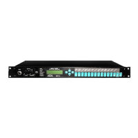
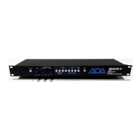
Front Panel (L to R)
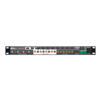
[1] Input Accepts unbalanced 1/4" phone instrument inputs. Maximum
level: +12.2 dBV (3.4 volts RMS). This input overrides the rear
panel input.
[2] Output Level control Final adjustment of output level. Follows all software level
controls.
[3] Output Clip LED Indicates overload of output stage.
[4] Room EQ control Applies tone shaping to compensate for the acoustic effects of
different performing venues. Normal setting is straight up (12
o'clock).
[5] Comp Thresh LED When Compressor is switched in, indicates that the signal is
exceeding the compressor threshold.
[6] Signal LEDs When glowing green: indicates the signal present in that
section is 30 dB below clip level. When glowing red: indicates
signal present in that section in 3 dB below clip level.
NOTE: The Signal LEDs will illuminate regardless of that section's Status (i.e. switched
in or out.
[7] Character display 2-rows by 16-characters LCD. Shows status and error
messages. Play mode: shows bank and number of current
program. In Controller panel mode, shows mapping of MIDI
program change number to MP-2 User program number.
Program and System Edit modes: shows parameter editing
information.
8] Arrow buttons Left/Right arrows:
used to move cursor be tween parameters
and screens in Program and System Edit modes.
Up (YesVDown (No) arrows:
used to adjust the value of the
currently selected parameter, execute a function, or answer a
query.
[9] Bank Select buttons In Play mode, increases (Bank Up) or decreases (Bank Down)
the bank number from which a program may be called.
[10] Number buttons (0-9) In Play mode, selects which program in a bank will be recalled.
[11] Preset/User button In Play mode, switches between factory Preset program banks
and User program banks.
[12] Program Edit button Enters and exits Program Edit mode. Initiates Store function
when exiting Program Edit mode. LED is lit when in Program
Edit mode.
[13] System Edit button Enters and exits System Edit mode. LED is lit when in System
Edit mode.
Page: 10