Configuration and Activation 4-93
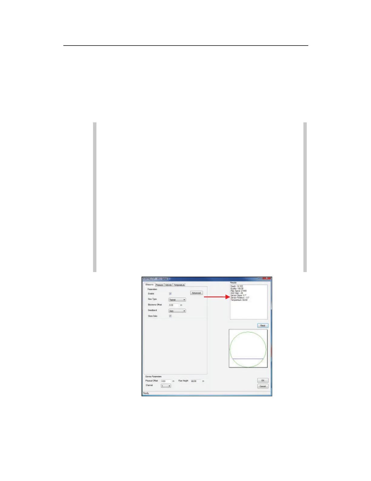
The monitor takes the sensor measurements and displays the
readings in the Results window. The results may include the
specific reading (e.g., depth or velocity), the quality of the
reading, the maximum signal strength, and the temperature.
When taking depth measurements, the dialog also displays a
cross section of the pipe, offering a visual perspective of the
depth of the flow.
Note: Pressure depth readings compensate for the
physical and electronic offsets, and the Automatic
Pressure Calibration value (PRESSK and PRESSK2).
Note: After an AV|Gated, AV|Max, ParaDepth or
ParaFlow sensor installation, the sensors must be verified
as being properly installed within the +/- 5 degrees from
the bottom center of the pipe. Following the monitor
activation, get online with the monitor, select the
AV|Gated or AV|Max/Peak Combo Ultrasonic tab or the
Smart Depth tab for the ParaDepth or ParaFlow sensor
and Read. Once the values display in the Results, review
the Sensor Slope and Sensor Rotation values and
determine if they are within +/- 5 degrees of 0 (as in the
following picture). Strive to have Sensor Slope and
Sensor Rotation as close to 0 degrees as possible.
Review the AV|Gated or AV|Max Ultrasonic Sensor Slope and Sensor
Rotation values