Analog and Digital I/O 9-9
signal wiring. Setup may involve penetrating existing
enclosures, running conduit, or sealing glands.
2. Establish the range and engineering units representing 4 to
20mA for the analog output, and then configure the
Analog Output 1 (or 2) component of the XIO Device
through Qstart
XML
with the analog output parameters that
indicate the values or measurements that correspond to the
analog signals within the 4-20mA range. Refer to Chapter
4, Configuration and Activation, for instructions on
supplying this information in Qstart
XML
.
3. Configure the device or instrument receiving the analog
signals with the range and engineering units corresponding
to the 4-20mA from the TRITON+.
4. Connect the analog output wires (from the customer-
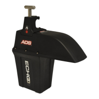
supplied cable) to the ADS XIO in the following way:
Note: Make sure the power is turned off to the third-party
device and XIO.
Release the latches and open the clear, front door on
the XIO.
Run the wires up through the left cable gland on the
XIO into the enclosure. ADS recommends using 18-
gauge wiring. You may need to loosen the plastic nut
on the cable gland on the outside of the XIO to feed
the wires through.