Installation
61287722G1-5B 17
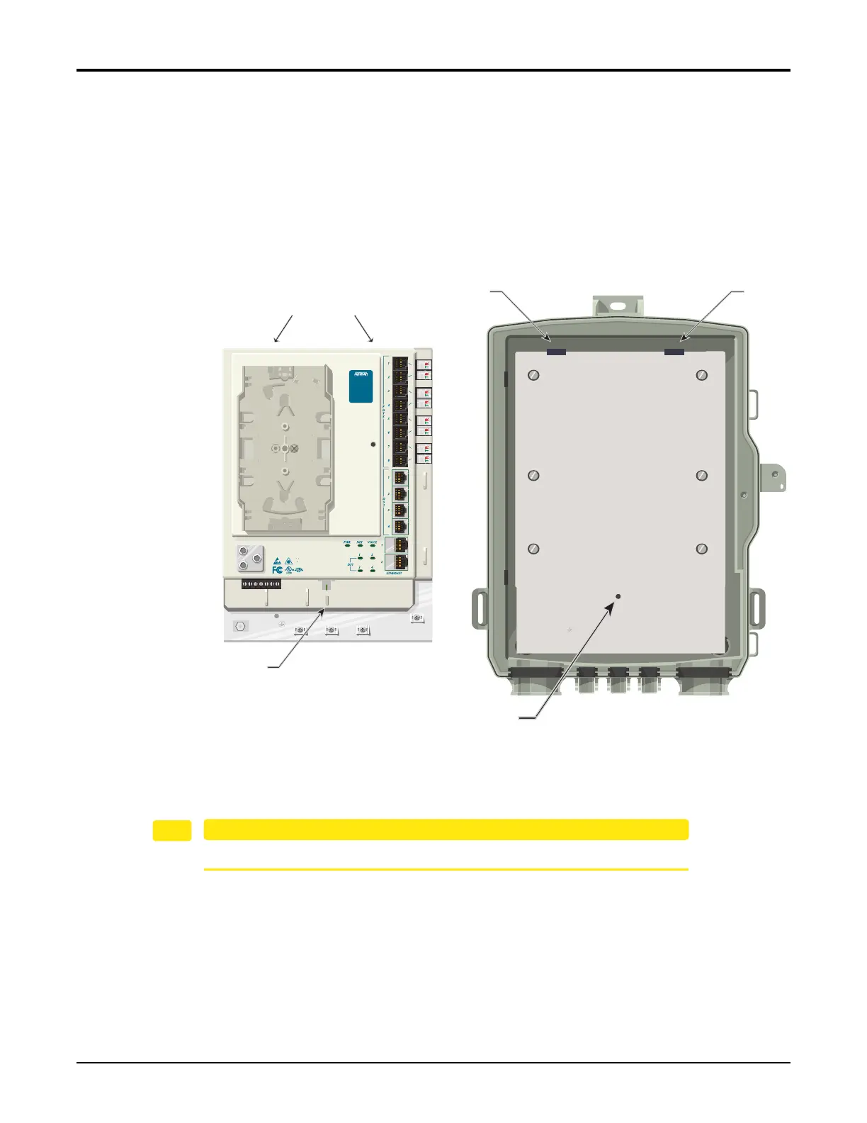
Install the Electronics Module
TheElectronicsModulehasaprotectivecoverthatpreventsaccesstothePOTS,Ethernetand
DS1connections.Toaccesstheseconnections,loosentheTelcoAccessscrewontheprotective
cover,thedooropenstotheleft.
RefertoFigure6wheninstallingtheElectronicsModuleintheEnclosure:
1. Aligntheslotsontherev
erseoftheElectronicsModu
lewiththetabsontheEnclosure.
2. SlidetheElectronicsModuleontothetabsandaligntheScrewSlotwiththethreaded
holeinthebackplate.
Figure 6. Installing the Electronics Module
3. SecuretheElectronicsModuleusingthe#6screw(P/N3276003003‐E)provided.
EnsuretheSBUONTisgroundedbeforemakinganyotherconnections.
Screw Slot
Threaded Hole
Slots on Reverse
Tab
Tab
TELEPHONE TROUBLESHOOTING:
1. Identify the bad line (POTS 1-8).
2. Plug any working phone into
the appropriate jack.
If the telephone works, the unit
is functioning normally.
If the telephone does not work,
contact your service provider.
3. Remove the telephone from the
POTS jack.
TOTAL ACCESS 372
1287722G1
Backplate