Total Access 372 Small Business Unit ONT Installation and Maintenance Guide
28 61287722G1-5B
RefertoTable7forEthernetLEDIndications.
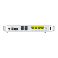
Install DS1 Connections
FortheDS1Connections,refertoFigure14onpage27andTable8tocompletethefollowing
steps:
1. RoutethewiresthroughthesamecableentryasthePOTScables.
2. StripbackthejacketofaCAT5or6cable.
3. ConnectthewirestotheRJ‐45connectorsusingaRJ‐45cr
imper.
4.
InserttheRJ‐45connectorsintheappropriateDS1socket.
RefertoTable8foralistofDS1CablePin‐Outs.
6TRD1‐ Transmit/ReceiveNegative Green
7 TRD3+ Transmit/ReceivePositive White/Brown
8TRD3‐ Transmit/ReceiveNegative Brown
Table 7. Ethernet LEDs
Label Indication Description
Link
{
z
Off
Green
LinkisdownorAdministrativelyshutdown
10/100/1000linkisup
Activity
{
4
Off
YellowFlashing
LinkisdownorAdministrativelyshutdown
TXorRxactivity
Table 8. DS1 Cable Pin-Outs
DS1 RJ-45 Pin-out
Pin Name Description
1RXRING Receivedatafromtheendcustomer(CPE)
2RXTIP Receivedatafromtheendcustomer(CPE)
3
–
NotUsed
4TXRING Transmitdatatowardtheendcustomer(CPE)
5TXTIP Transmitdatatowardtheendcustomer(CPE)
6‐8
–
NotUsed
Table 6. Ethernet Cable Pin-Outs (Continued)
Ethernet RJ-45 Pin-out