Total Access 372 Small Business Unit ONT Installation and Maintenance Guide
40 61287722G1-5B
•Ifthemeasurementresultsarewithinrange,performthestepsin“UpstreamSignal
LevelVerification”onpage 40.
Upstream Signal Level Verification
AvalidopticalpowerleveldeliveredbytheSBUONTmustbereceivedbytheOLTinburst
modeat1310nmthatiscontrolledintheupstreamdirectionbygrantsgivenbytheOLT.
Theindividualopticalpowerlevelthatshouldbepresentattheopticalbulkheadthatis
locatedontheSBUONTisli
st
edinTable12.
Toverifythecorrectupstreamopticalsignallevelispresent:
1. Ensureallconnectorsarecleananddry.Refertothe“CleaningandInspectionofCompo‐
nents”onpage 38fordetails.
2. SetupandcalibrateanOPMorOLTSthatcanbeplacedinlineontheopticalfibe
randis
capableofperformingwavelengthfilteringinordertoobtainindividualwavelength
opticalpowerlevelreadings.
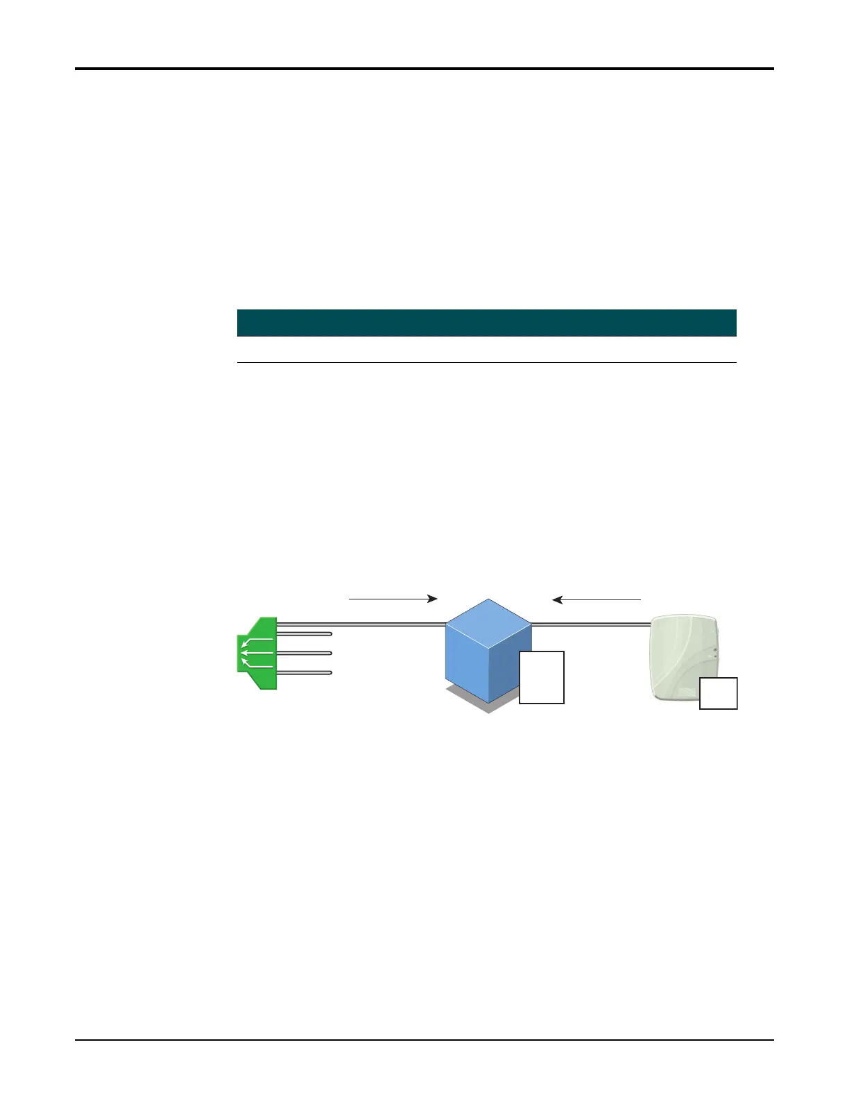
3. Connectthetestequipmenttotheopticalfiberdropcableandtheopticalbulkheadon
theSBUONTusingatestjumperasshowninFigure20onpage40.
Figure 20. Upstream Test Configuration
4. Verifythetestequipme
n
tmeasurementresultsarewithintheopticalsignallevelrange
describedinTable12above.
5. Ifthemeasurementresultsarewithinrange,performaverificationofthe provisioningof
theSBUONTattheOLTandverifythattheproperupstreamsignallevelisbeing
receivedbytheOLT.
6. Ifthemeasuremen
tresultsarenotwi
thinrange,performaverificationofthe
provisioningoftheSBUONTattheOLT.Ifafterverifyingtheprovisioningtheproblem
stillexists,replacetheSBUONT.
Table 12. Upstream Power Levels
Optical Wavelength Minimum Power Level Maximum Power Level
1310nm 0dBm +5dBm
1310 nm
1490 nm
Test jumper
Drop cable
OPM
or
OLTS
ONT