Installation
61287722G1-5B 23
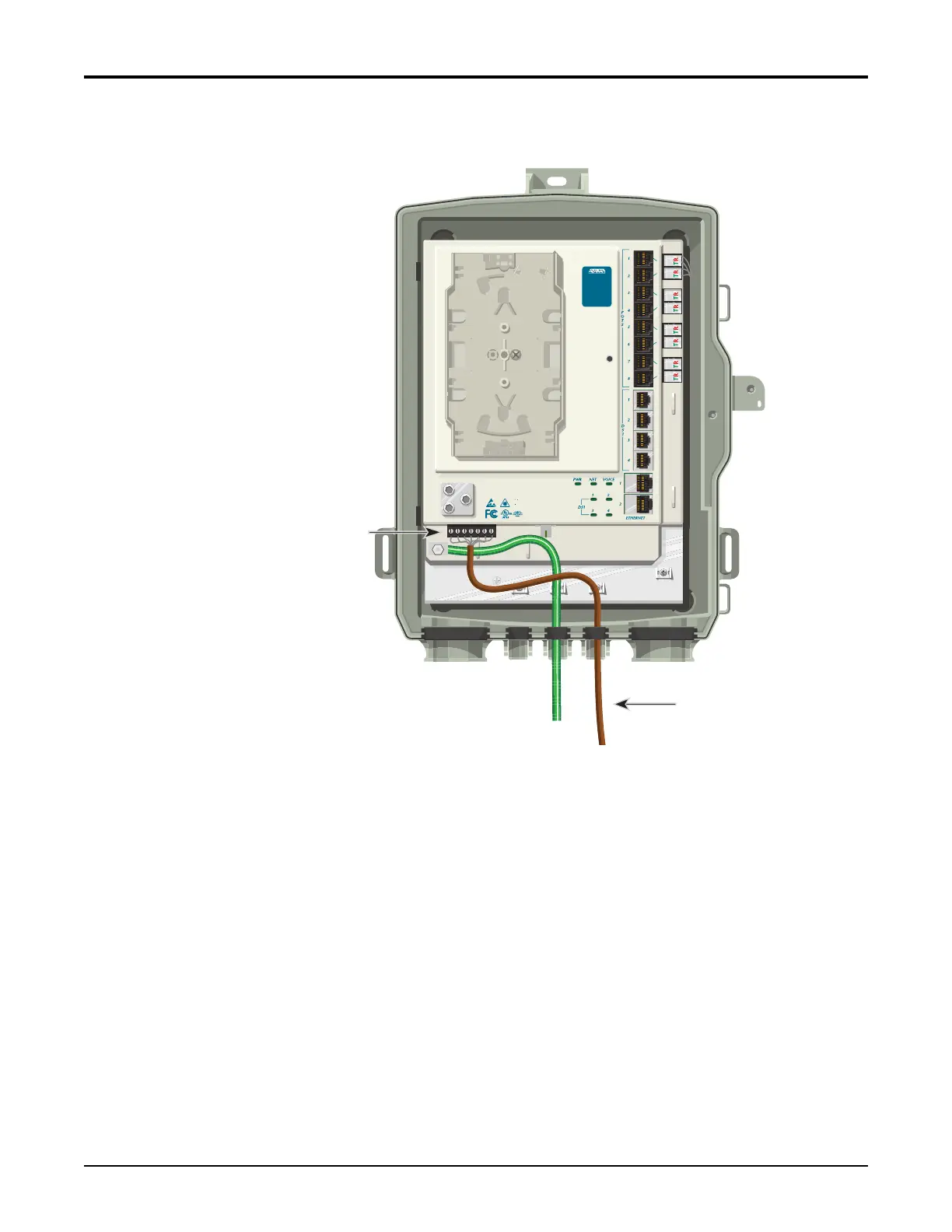
4. Removetherubbergrommetfromthehousingandroutethewiresthroughtherubber
grommet(seeFigure11).
Figure 11. Power/Alarm Connector
5. Toterminatethe2Powerleadsand,andifneeded,the5alarmstatusleads,cutwireto
lengthandstriptheinsulationback1/4inch(0.64cm).
6. LooseneachretainingscrewontheP
ower/AlarmConne
ctorandinsertthewiresinto
theirappropriateterminals(refertoTable 4onpage 22).
7. Tightentheretainingscrews.
8. ReinstallthePower/AlarmConnectorintheElectronicsModule.
9. Routethecableasshownabove.Ifnecessary,tiewrapthemtotheappropriateanchor
points.
10. Reinstalltherubbergrommet.
Power (Brown)
Power/Alarm
Connector
TELEPHONE TROUBLESHOOTING:
1. Identify the bad line (POTS 1-8).
2. Plug any working phone into
the appropriate jack.
If the telephone works, the unit
is functioning normally.
If the telephone does not work,
contact your service provider.
3. Remove the telephone from the
POTS jack.
TOTAL ACCES S 372
1287722G1