Installation
61287722G1-5B 27
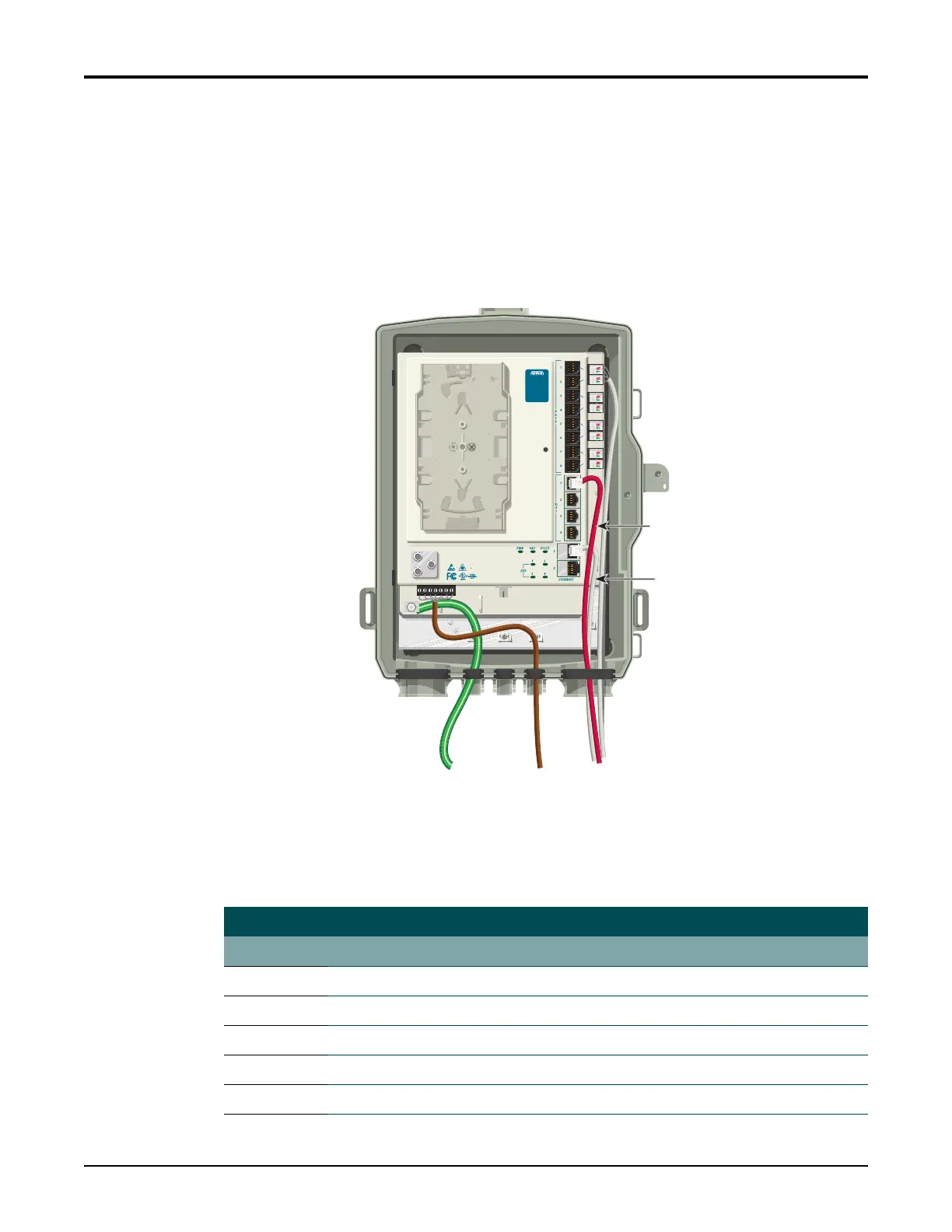
Install Ethernet Connections
TheSBUONTsupportstwoGigabitEthernetports.ThecableusedshouldberatedCAT‐5or
6.ForEthernetconnectionsrefertoFigure14and Table6tocompletethefollowingsteps:
1. RoutetheSubscriberEthernetwiresthroughthesamecableentryasthePOTScables.
2. StripbackthejacketofaCA
T5
or6cableandconnectthe4pairtwistedwirestotheRJ‐
45PlugusingaRJ‐45crimper.
3. InserttheterminatedRJ‐45jackintotheappropriate
ETHERNET 1–2socketontheSBU
ONT.
Figure 14. Ethernet and DS1 Cable Connections
RefertoTable6foralistofEthernetCablePin‐Outs.
Table 6. Ethernet Cable Pin-Outs
Ethernet RJ-45 Pin-out
Pin Name Description ColorCode
1 TRD0+ Transmit/ReceivePositive White/Orange
2TRD0‐ Transmit/ReceiveNegative Orange
3 TRD1+ Transmit/ReceivePositive White/Green
4 TRD2+ Transmit/ReceivePositive Blue
5TRD2‐ Transmit/ReceiveNegative White/Blue
Ethernet
Connection (White)
DS1
Connection (Red)
TELEPHONE TROUBLESHOOTING:
1. Identify the bad line (POTS 1-8).
2. Plug any working phone into
the appropriate jack.
If the telephone works, the unit
is functioning normally.
If the telephone does not work,
contact your service provider.
3. Remove the telephone from the
POTS jack.
TOTAL ACCESS 372
1287722G1