5700512-C Product Overview 2-3
Series FC-77X / 77XX, Series FC-78X / 78XX, and Series FC-79X MFCs
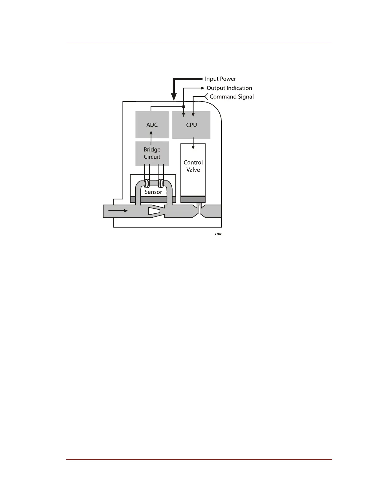
Figure 2-2. MFC functional block diagram
Flow Sensor Assembly
The flow sensor consists of a capillary tube wound by two self-heating resistance
wires through which electrical current is passed. The resistance wires heat the sensor
tube and when gas flows through the flow sensor a temperature differential is
produced between the upstream and downstream wires. The temperature change
causes a change in resistance which is detected as an electronic signal by the bridge
circuit of the electronics assembly.
The MFC uses the mass gas flow measurement because the heat exchange between
the gas and the self-heating resistance wire depends on the mass flow. When gas is not
flowing, heat is distributed evenly over the upstream and downstream wires, therefore
the resistance of upstream and downstream wires is equal and the bridge circuit
outputs zero. When gas flows, heat is exchanged between the gas and the self-heating
resistance wires. The temperature distribution between the upstream and downstream
resistance wires changes causing an imbalance. The imbalance of the upstream and
downstream temperatures results in a resistance differential that is detectable by the
bridge circuit as an electronic signal. The electronic signal represents the mass gas
flow.
 Loading...