5700512-C Specifications and Reference Information 6-33
Series FC-77X / 77XX, Series FC-78X / 78XX, and Series FC-79X MFCs
Specifications for Model FC-785Y-B MFCs
The following table lists specifications for the FC-785Y-B MFCs.
MFC DIMENSIONS
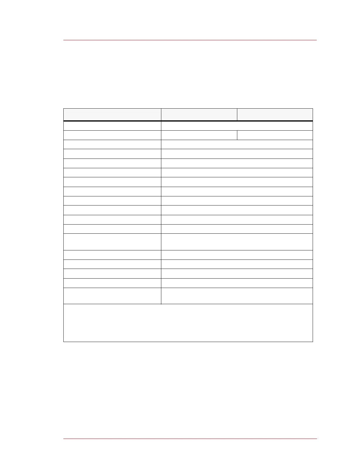
Table 6-32. Specifications for FC-785Y-B series MFCs
Specification FC-785Y-B FC-785CY-B
Full-scale range (N
2
equivalent) 10 sccm to 5000 sccm
Valve type Normally open Normally closed
Response time Maximum ±2% of full scale, within 1 s
Accuracy
Note 1
Maximum ±1% of full scale
Linearity Maximum ±0.5% of full scale
Repeatability Maximum at ±0.2% of full scale
External leak rate Maximum 1 x 10
-11
[Pa*m
3
/sec(He)]
Flow rate control range 2% to 100%
Operating pressure range 49 to 275 kPa(D); 7 to 40 psi(D)
Proof pressure
Note 2
981 kPa(G); 142 psi(G)
Operating temperature 5ºC to 45ºC (41ºF to 113ºF)
Flow rate setting and output signal 0 VDC to 5.0 VDC
Supply power Minimum +15 VDC ±2% 25 mA
Minimum -15 VDC ±2% 180 mA
Power consumption Maximum 3.1 W
Gas-wetted surface material SUS316, SUS316L, PTFE, Ni, KM-45
Mounting position Any direction
Weight 1.3 kg (2.9 lb)
Options Current output (0 mA to 2.5 mA), error detection, TC surface
treatment
Note 1—Accuracy ensures that the calibration gas equivalent flow is ±1% of full scale when 22 ± 3ºC
in temperature is obtained for the primary reference in the specified operating pressure range. If the ser-
vice gas and calibration gas are the same, the measured gas is ensured to be ±1% of full scale in the
specified operating pressure range as to our primary reference.
Note 2—The proof pressure specification does not ensure operation or accuracy.
 Loading...