4-2 I/O Connections and Communication 5700512-C
Advanced Energy
®
Honda Connector
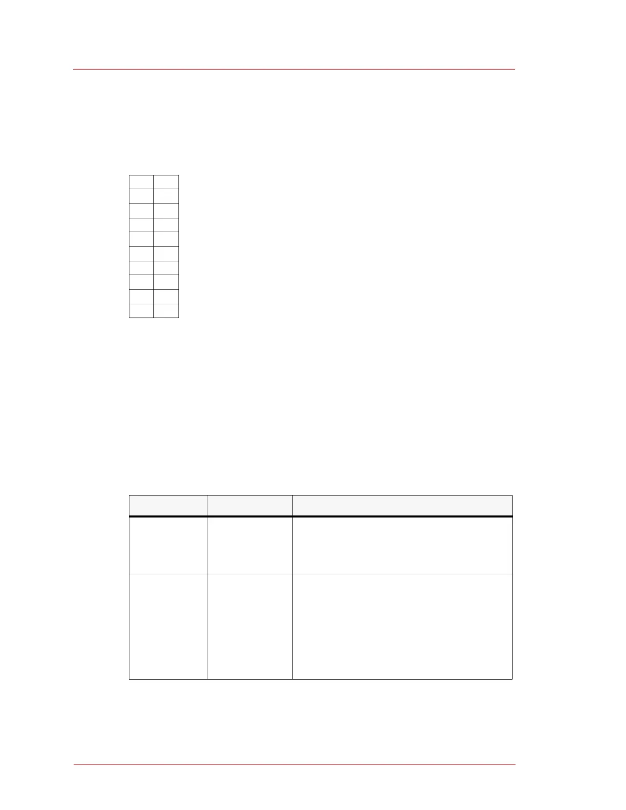
Figure 4-2 shows the pin numbers on the 20-pin Honda connector.
Figure 4-2. 20-pin Honda connector
20-Pin Connector Signal Descriptions
Table 4-1 provides the pin and signal descriptions for the 20-pin card-edge connector
and the 20-pin Honda connector.
11 1
12 2
13 3
14 4
15 5
16 6
17 7
18 8
19 9
20 10
Table 4-1. 20-pin connector signal descriptions
Pin Signal Name Signal Description
1 CASE GND Case ground terminal. This terminal is
connected to the base of the MFC. All other
terminals must be insulated from this
terminal.
2 POWER
COMMON
Common line that carries the majority of the
MFC operating current.
Note: POWER COMMON (pin 2) and
SIGNAL COMMON (pins B and C for
the card edge connector, pins 12 and 13
for the Honda connector) must be
connected at the power supply.
 Loading...