5700512-C I/O Connections and Communication 4-3
Series FC-77X / 77XX, Series FC-78X / 78XX, and Series FC-79X MFCs
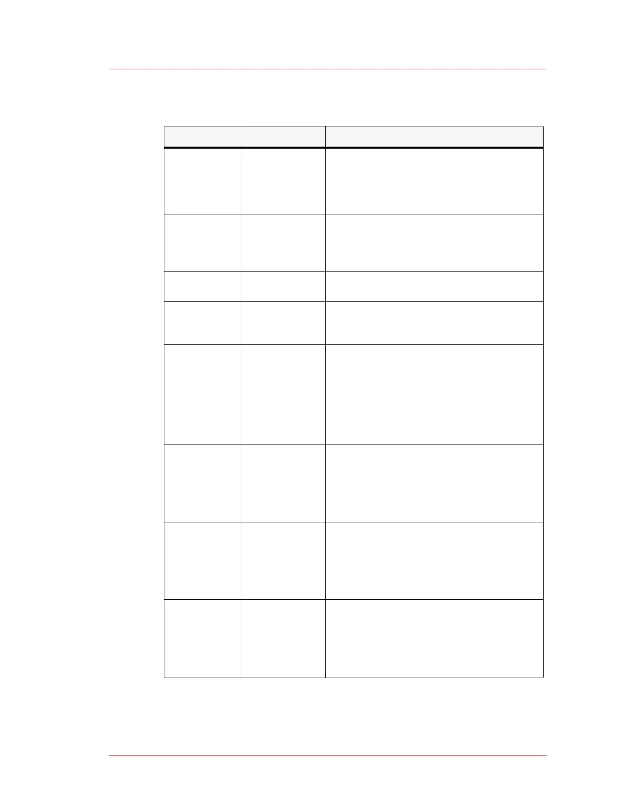
3 OUTPUT Flow output terminal. Flow is represented by
a signal scaled between 0 VDC and 5 VDC:
•0 VDC = 0%
• 5 VDC = 100% of full-scale flow
4 +15 VDC For specifications on this signal, see the
supply power section of the specifications
table for the specific MFC model (see “Model
Specifications” on page 6-1).
5 UNASSIGNED This pin is unassigned and should not be
connected.
6 VALVE TEST
POINT
Terminal for monitoring the voltage of the
valve drive. The scale is 0 VDC to -13 VDC
(maximum valve voltage).
Key (card
edge)
7 (Honda)
KEY
or
UNASSIGNED
The key is a slot in the card-edge connector
that ensures the connector can not be
connected backwards.
For Honda connectors, this pin is unassigned
and should not be connected.
8 ALARM H This pin provides an alarm output, which does
not need to be connected. For more
information see “Alarm Output (Error
Detection) Signals” on page 4-7.
9 ALARM L This pin provides an alarm output, which does
not need to be connected. For more
information see “Alarm Output (Error
Detection) Signals” on page 4-7.
10 ALARM OFF This pin resets the alarm signal on pins 8 and
9. It does not need to be connected. For more
information see “Alarm Output (Error
Detection) Signals” on page 4-7.
Table 4-1. 20-pin connector signal descriptions (Continued)
Pin Signal Name Signal Description
 Loading...