BYB User Manual Page 7 of 55 PN: 90020 Version: 1.4
Floor Requirements:
Visually inspect the floor where the lift is to be installed and check for cracked or defective concrete.
This lift must be installed on a level concrete floor with no more than 3 degrees of slope and in good
condition. Consult a qualified person to address concrete conditions, seismic loads and local or state
requirements. This lift has been designed to be installed on a minimum of 4-inch thick, 3000 psi
concrete cured 28 days. Do not install this lift on asphalt, wood, or any other surface other than
described.
Notes:
DO NOT use this lift outdoors, doing so will void the warranty. The lift is not designed to be used in a
wet or damp environment or sit in standing water. Ensure drainage to keep water away from the lift.
DO NOT begin installation in a tight area; give yourself plenty of space to work safely. It is
recommended to leave at least 24 inches on each side of the lift and 24 inches behind the lift to
install the safety rod under the runway (figure 1.3 & 1.4). The minimum ceiling height required for
installation is 9-feet for XT, WF, WB/BB & BT lifts and 8-feet for CL lifts. Calculate clearance based
on your vehicle height plus the maximum lifting height.
It is NOT recommended to anchor this lift. If you must anchor the lift, follow the instructions on page
38. The owner is responsible for following any local or state seismic anchoring requirements. If the
concrete floor is a post-tensioned slab, contact the architect before drilling.
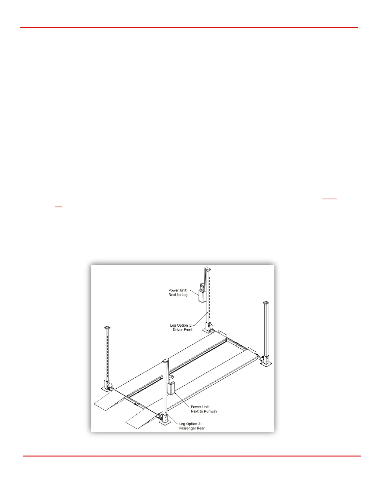
Power Unit Locations/Assembly View:
The Power Unit may be placed on one of two legs, either driver’s side front or passengers side rear
(figure 1.1). On the chosen leg, the Power Unit may be rotated to either the inside, next to the
runway or outside, next to the leg.