BYB User Manual Page 27 of 55 PN: 90020 Version: 1.4
Tips and Troubleshooting Lock Linkages
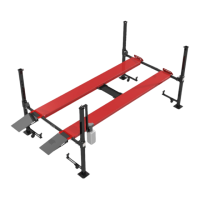
Install the spring from the hardware box onto the eyebolt and washer welded on the long 3/8 Round Rod.
With the lock opposite the T-bar installed and the T-bar pointed up and down (12’o clock) on both the front
and back Crossmembers, adjust the top hiem in figure 5.5 so the hole in the hiem and T-bar line up. Install
the 3/8-24 SCHC and nut, placing the split washer BETWEEN the T-bar and Hiem joint.
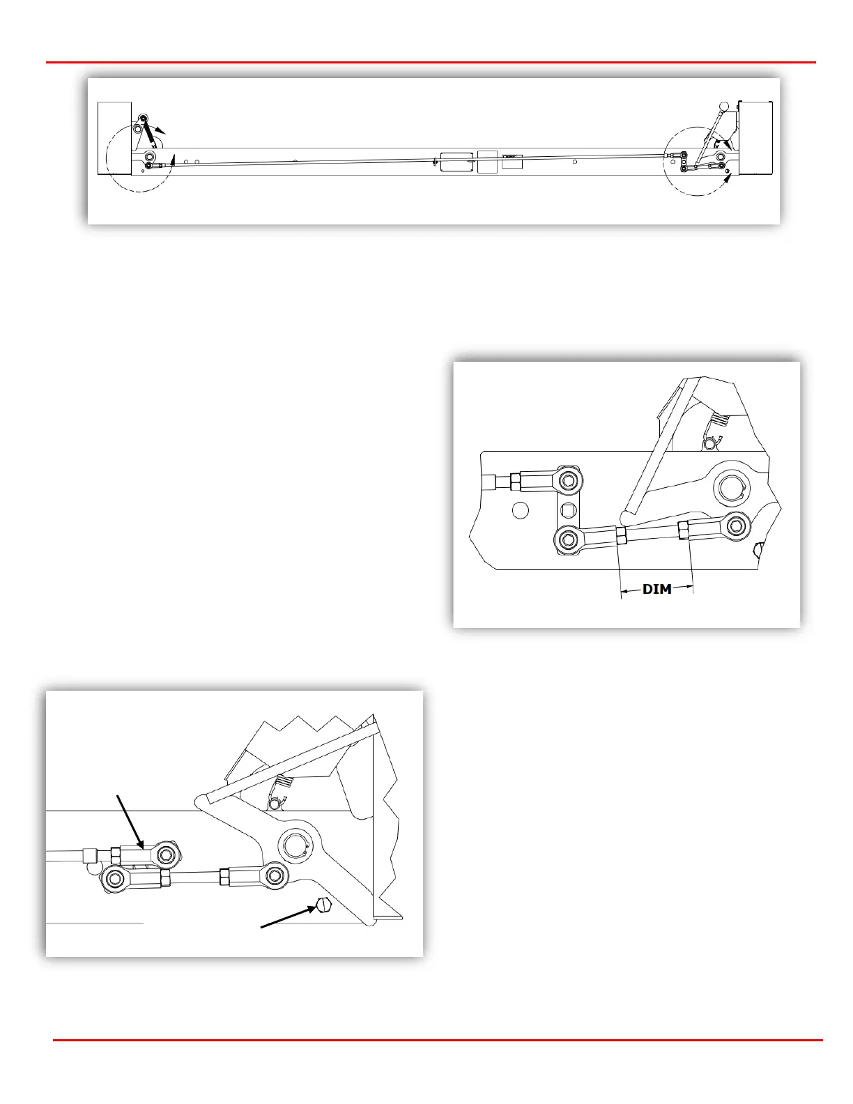
Once installed, the lock linkages will need
adjusted. Start with the dimensions shown below
for the all-thread pieces on both Crossmembers.
These dimensions are just a starting point.
NOTE: the dimensions shown are taken from the
end of the hiem to the end of the opposite hiem.
CL/XT/BT: DIM = 2.4375 (2-7/16)
WF/WB/BB: DIM = 10.5 (10-1/2)
TIP 1: The T-bar needs to fully collapse to produce
the most amount of travel. Ideally the T-bar should
be almost horizonal when the Lock Handle is pulled
to release the Locks (see figure 5.6).
Tip 2: To get MORE lock travel, the All-thread needs
to be LENGTHENED. The longer the All-thread, the
more travel. CAUTION: if the All-thread assembly is
adjusted is too long, it may bend the T-bar. Always
make minor adjustments and test.
Tip 3: When properly adjusted, all locks will release,
and the Lock Handle will not touch the Stop Bolt
(see figure 5.6).
Tip 4: If the Hiem joints do not fully rotate, make
sure the split washer is installed between the hiem
and mating surface NOT on next to the nut.
of Stop Bolt