BYB User Manual Page 26 of 55 PN: 90020 Version: 1.4
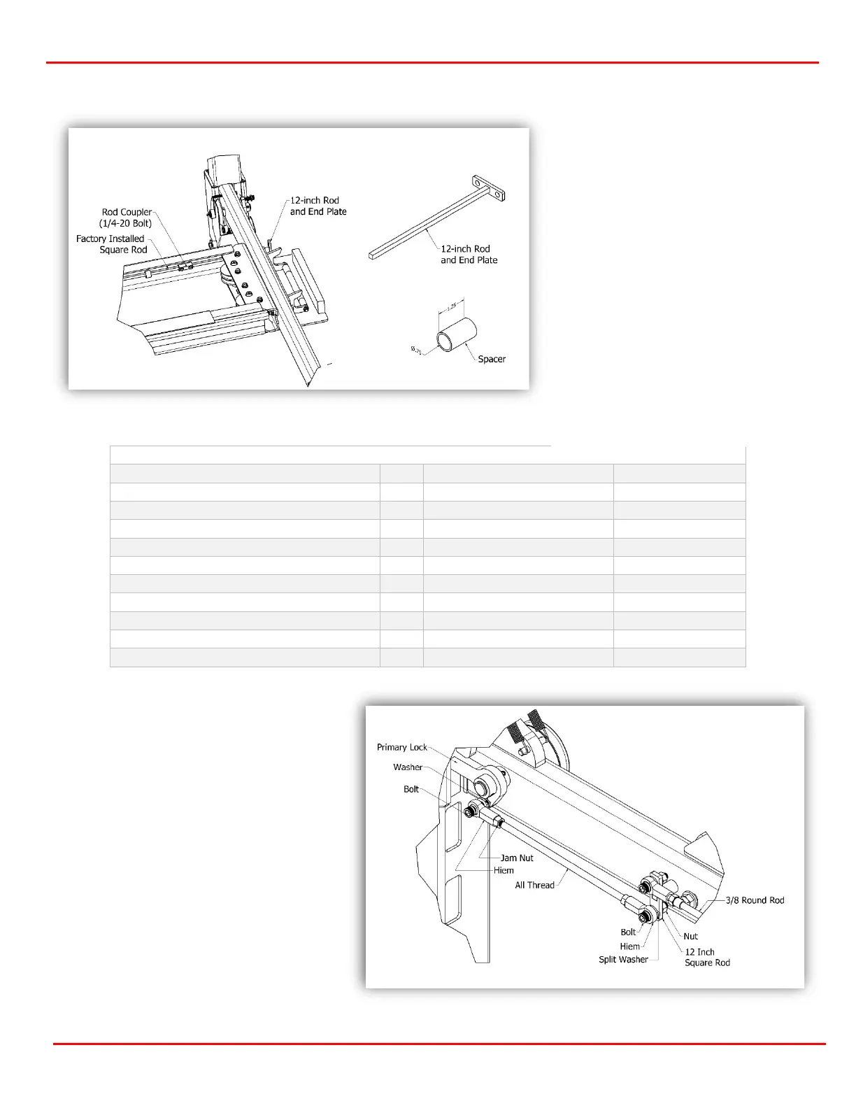
Lock Linkage Rod Installation
Square Coupler (pre-installed)
Gather the parts shown in Table 5-1
from the hardware bag.
Select the (2) 3/8 x 3.875 or 11.875
pieces of all thread. Install a 3/8-24
nut and then a 3/8 hiem joint on to
each end (figure 5.3).
Select the (2) 3/8 long Round Rods
(zip tied to the square rod in the
power runway) and slide through the
eyebolts (Figure 5.4). After installed,
thread a 3/8-24 jam nut and hiem
joint on either end of the rod.
Insert the opposite end of the all-
thread assembly into the primary
lock as shown (figure 5.4 & 5.5).
Attach with a split washer
BETWEEN the hiem joint and lock
and install the nut on the back side
of the lock.
Note: Leave the jam nuts loose until
all 4 ends are installed.
Install the hiem joint on the
opposite side of the 3/8 Round Rod
using the same 3/8 split washer
between the T-Bar and Hiem, then
install the 3/8-24 nut. Perform this
on both crossmembers.
Rotate the lock/handle assembly so
that the safety rod end plate side
points to 12 o’clock (Figure 5.3)