BYB User Manual Page 23 of 55 PN: 90020 Version: 1.4
The crossmember and legs are extremely heavy, a material handler may be used to assist in raising the
assembly. To prevent the crossmember from riding up the legs place a stop in the lock hole directly above
the crossmember. The stop can be a piece of metal, prybar screwdriver, etc. take care not to drop the stop
into the leg while lifting.
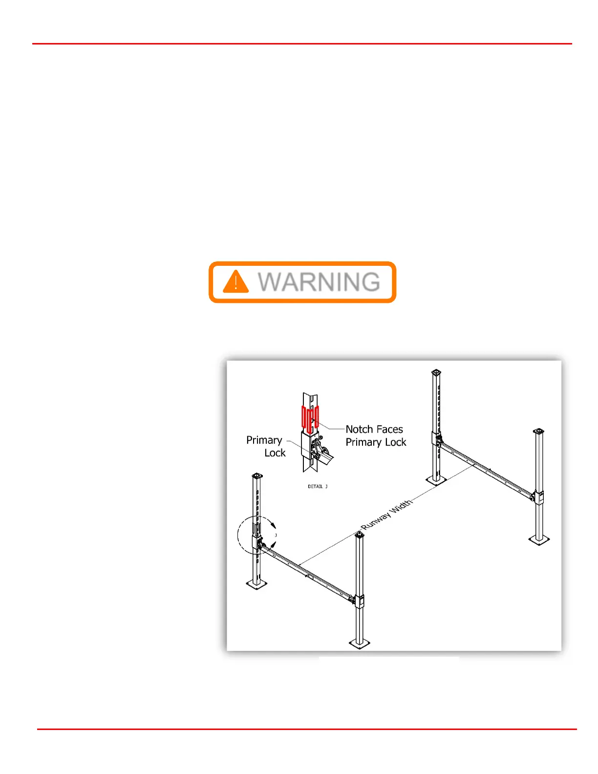
The next section can be assembled and raised. Take note the leg holes must face towards the outside of the
lift on both sides (figure 3.7)
Install the remaining UHMW glide blocks. Remember 4 are cut to fit the locks (figure 3.9).
The UHMW glide blocks may be a tight fit. Wiggle the legs slightly to help with alignment, making it easier to
install.
If it’s still snug, use a wood block and a hammer to tap them down flush. Install the Glide Block Retainers as
shown in figure 3.19 with 1/4-20 bolts and washers.
Front and Back Locations
The front and back sections
(shown as “Runway Width” in
Figure 3.9) should be positioned
approximately to the dimensions
below.
CL, XT: 152.625
WF, WB, BB, BT: 192.875
After positioning, check
squareness by measuring
diagonally between the front and
back sections. Adjust until both
numbers are the same. This will
square up the lift.
Figure 3.9 Up righting one Section